Digital pulse width modulation

a digital pulse and width technology, applied in pulse generators, pulse manipulation, pulse techniques, etc., can solve the problems of increasing the current consumption of digital circuits, the level of computational complexity, and the most difficul

Active Publication Date: 2006-02-14
MOTOROLA SOLUTIONS INC
View PDF2 Cites 27 Cited by
  • Summary
  • Abstract
  • Description
  • Claims
  • Application Information

AI Technical Summary

Problems solved by technology

Generally speaking, most higher frequency PWM systems have been implemented using analog circuitry due to the high level of computational complexity in accurately processing the edges of the pulses in the pulse stream at high speeds.
This is particularly true when both edges are varied as in the third and fourth variation, and is most difficult when both edges are varied independently.
Moreover, the higher the frequency of processing required, the greater the current consumption that digital circuits use frequently dictating that analog PWM circuits be used, particularly in battery powered communication equipment.

Method used


Image

  • Digital pulse width modulation
  • Digital pulse width modulation
  • Digital pulse width modulation

Examples


Embodiment Construction

[0017]While this invention is susceptible of embodiment in many different forms, there is shown in the drawings and will herein be described in detail specific embodiments, with the understanding that the present disclosure is to be considered as an example of the principles of the invention and not intended to limit the invention to the specific embodiments shown and described. In the description below, like reference numerals are used to describe the same, similar or corresponding elements in the several views of the drawings.

[0018]The terms “a” or “an”, as used herein, are defined as one or more than one. The term “plurality”, as used herein, is defined as two or more than two. The term “another”, as used herein, is defined as at least a second or more. The terms “including” and / or “having”, as used herein, are defined as comprising (i.e., open language). The term “coupled”, as used herein, is defined as connected, although not necessarily directly, and not necessarily mechanical...


PUM


Abstract

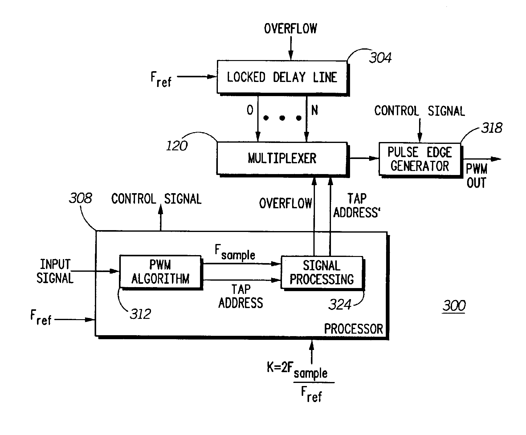
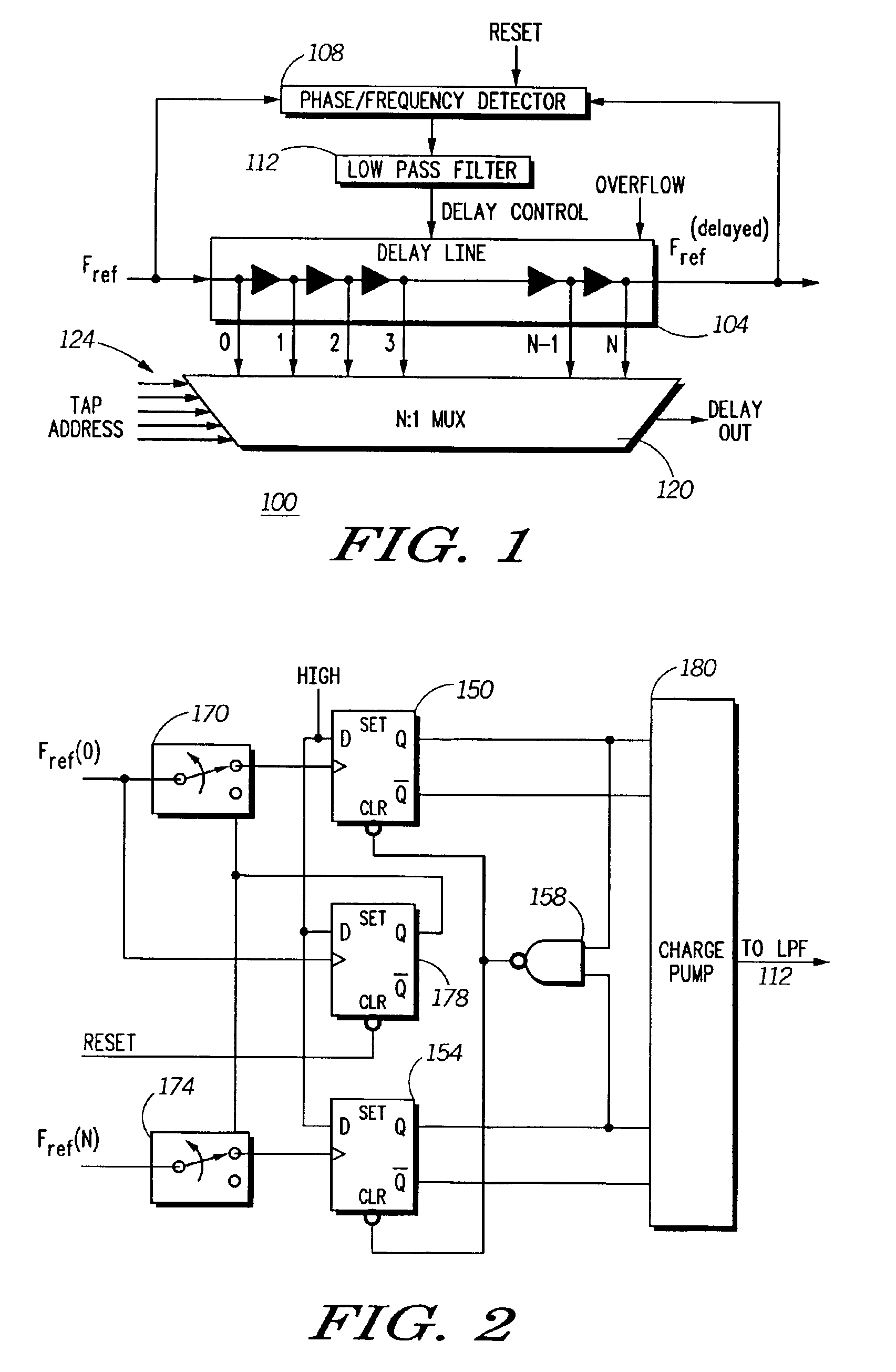
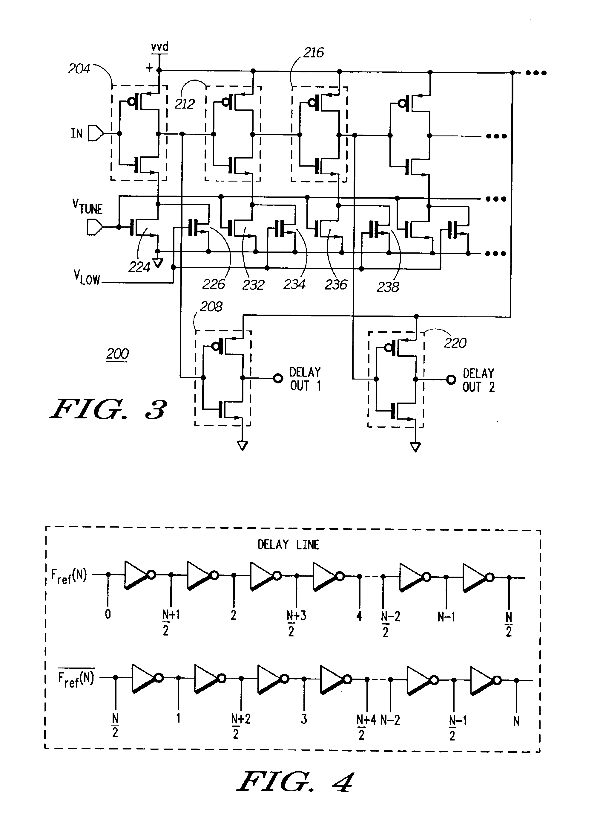
A digital technique for pulse width modulation (PWM) utilizes a tapped delay line 304 receiving a reference clock and generating a plurality of time delayed reference clock transitions having finer time resolution than the reference clock signal. A multiplexer 120 receives the plurality of time delayed reference clock transitions as an input thereto and producing an output when one of the plurality of time delayed reference clock transitions is addressed. An accumulator circuit 524 generates control timing signals associated with the input signal sampling rate Fsample that are used to select outputs from the delay line 304 representing a pulse width modulated output signal.

Description

FIELD OF THE INVENTION[0001]This invention relates generally to the field of pulse width modulation (PWM). More particularly, this invention relates to digital pulse width modulation.BACKGROUND OF THE INVENTION[0002]Pulse width modulation can be implemented in any one of four variations. In each case, an input signal is modulated in such a manner that the width of a pulse within a stream of pulses represents an amplitude of the input signal at a sampling time. In a first variation of PWM, the relative time of the rising edge of each pulse in the stream of pulses is fixed, and each pulse is varied in width by changing the timing of its falling edge. In a second variation of PWM, the relative time of the falling edge of each pulse in the stream of pulses is fixed, and each pulse is varied in width by changing the timing of its rising edge. In a third variation of PWM, the relative time of the center of each pulse in the stream of pulses is fixed, and each pulse is varied in width by c...

Claims


Application Information

Patent Timeline
Patent Type & Authority Patents(United States)
IPC IPC(8): H03K7/08H03K5/13H03L7/081H03L7/089
CPCH03K5/131H03K7/08H03K5/133H03L7/0891H03L7/0812H03L7/0816
Inventor STENGEL, ROBERT E.YU, WEN
Owner MOTOROLA SOLUTIONS INC
Why Eureka
Try Eureka