Access control system for a work vehicle

a work vehicle and access control technology, applied in the field of work vehicles, can solve the problems of unauthorized users easily “hotwire” these work vehicles and automobiles, many relatively simple work vehicles do and many relatively simple work vehicles have some degree of complexity

Inactive Publication Date: 2006-02-14
CNH IND AMERICA LLC +1
View PDF27 Cites 73 Cited by
  • Summary
  • Abstract
  • Description
  • Claims
  • Application Information

AI Technical Summary

Benefits of technology

[0007]In accordance with the first embodiment of the invention, a method for controlling access to a work vehicle having an engine, a transmission, auxiliary fluid actuators, and an control switch, is provided. The vehicle is accessible with a combined transponder and control key. The method includes activating a control switch with a control key, transmitting data indicative of an authorized level of access to a control system of the vehicle from the data transponder, comparing the transmitted data with data stored in the vehicle control system to determine an authorized level of access, and limiting access to the work vehicle by disabling at least two subsystems of the work vehicle.
[0008]The method of limiting access to the engine may include disabling at least one of the following subsystems: an engine ignition subsystem, an engine fuel subsystem, and an engine starting subsystem. The method of limiting access to the auxiliary fluid actuators may additionally include electronically preventing the operation of one or more of a swing actuator, a boom actuator, a dipper actuator, a bucket or tilt actuator; a front loader actuator, and a lift arm actuator. The method of electronically preventing access to the work vehicle may include preventing operation of a fluid actuator of a backhoe, a front loader, or other fluid actuated work vehicle implement. The method of controlling access to a work vehicle may also include communicating a message packet over a serial communication bus that couples at least two microprocessor based electronic controllers, wherein one of the two microprocessor based electronic controllers includes an auxiliary fluid controller coupled to the auxiliary fluid actuators.
[0009]In accordance with a second embodiment of the invention, a control system for controlling access to a work vehicle having an engine with engine subsystems, a transmission, and an auxiliary fluid controller coupled to and configured to control a plurality of fluid actuators is provided. A control key is configured to operate a control switch. A transponder, suc

Problems solved by technology

An unauthorized user can easily “hotwire” these work vehicles and automobiles.
This is a particular problem in work vehicles that have relatively simply access control systems.
Many relatively simple work vehicles do have some degree of complexity, in that they also have an electronic circuit that is responsive to operator command signals provided by manually moveable control levers and switches that cause the various fluid actuators on the work vehicle to move.
In any vehicle with dual disablement, an unauthorized user, such as a thief, would not only have to bypass or hotwire the security system preventing the engine from starting, but would also be required to independently and separately bypass or hotwire the electronic circuit controlling the auxiliary implements or the transmission (or both).
Only by over-coming both the engine and the second system disabling feature could an unauthorized operator start, move, and use the vehicle.
Thus, even if the unauthorized operator could hotwire the engine, his inability to also enable the auxiliary fluid system or the transmission system would make it difficult to operate the vehicle, particularly for example if the various fluid actuators were lowered to engage the ground or the transmission was disabled or in low gear.

Method used


Image

  • Access control system for a work vehicle
  • Access control system for a work vehicle
  • Access control system for a work vehicle

Examples


first embodiment

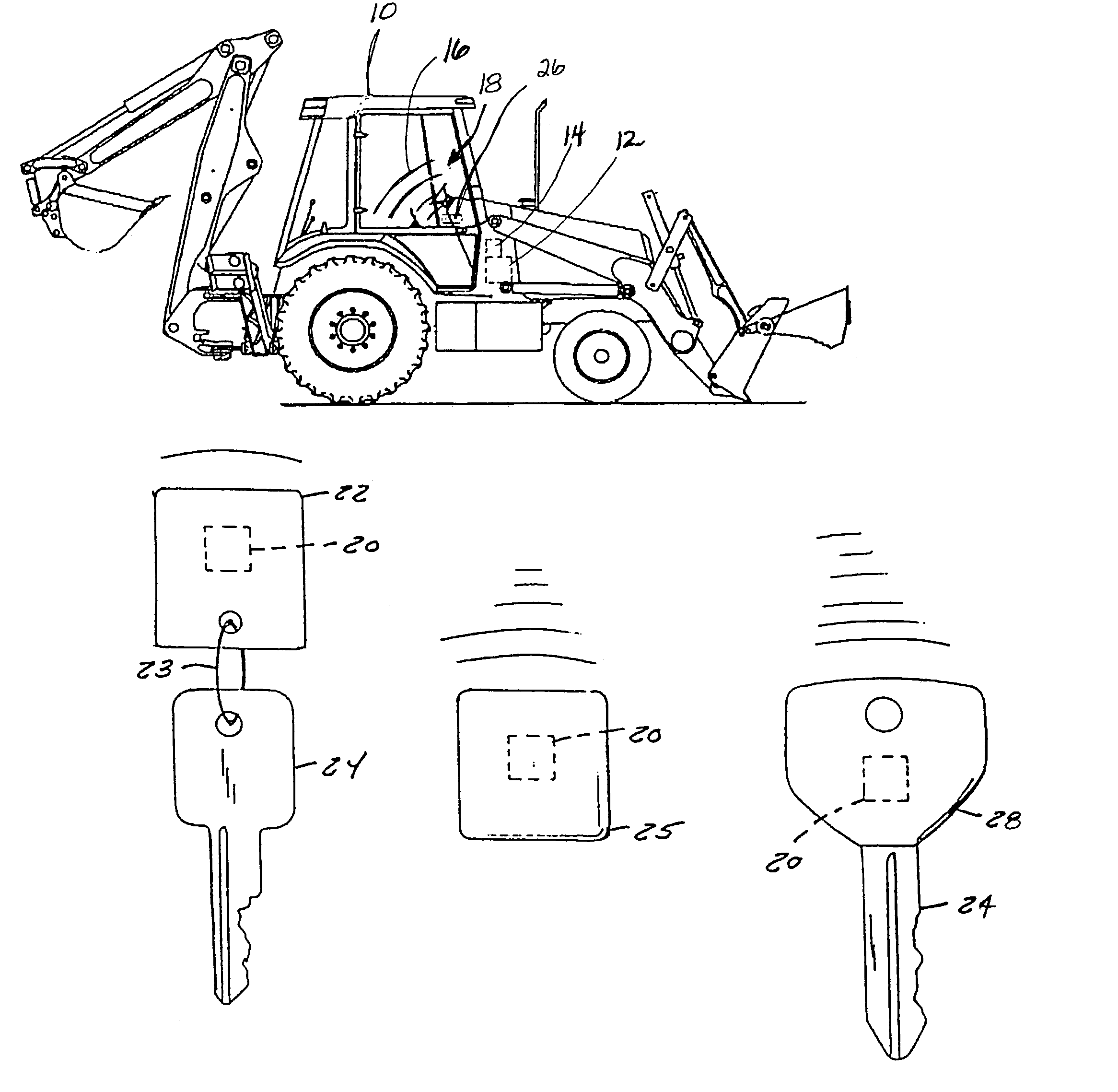
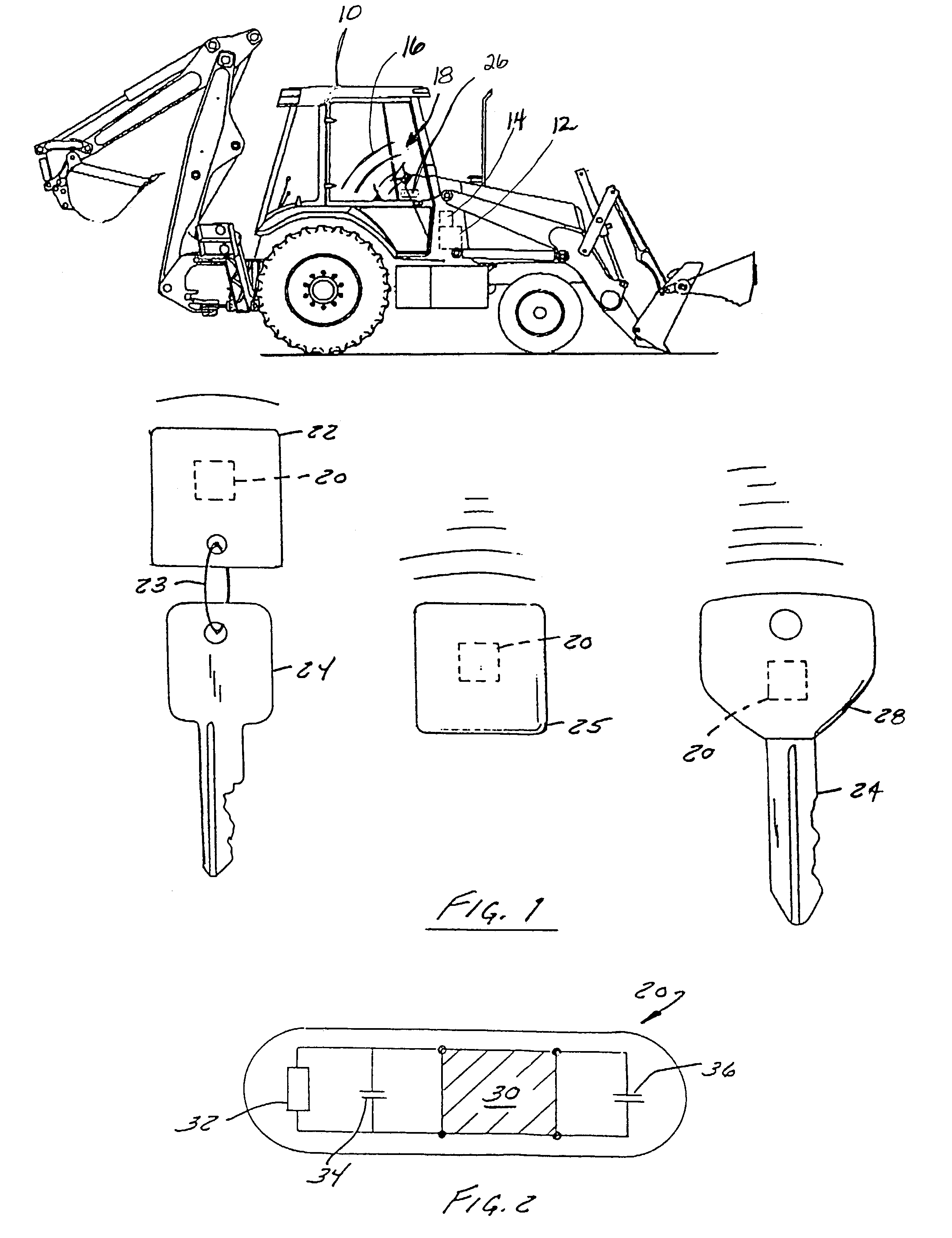
[0022]In a first embodiment, the data stored in the memory of microcontroller 30 may include numeric values that are remotely downloaded into the transponder 20 and indicate operating parameters of the work vehicle such as (1) a total distance which the work vehicle is permitted to travel, (2) a geographical area in which the vehicle may only be operated, (3) allowed times and dates of operation, such as (i) the specific hours during the day when the vehicle may be operated or (ii) the specific dates on which it may be operated, (4) the total time of authorized operation, and (5) the vehicle subsystems that the operator is authorized to use.

second embodiment

[0023]In a second embodiment, the data stored in microcontroller 30 of the transponder may also include data downloaded from the vehicle itself, such as (1) the distance traveled by the vehicle, (2) the date and times of specific events, such as the time the vehicle was started and the time the vehicle was stopped, (3) time-triggered elapse records, such as service reminders, and when a vehicle rental period expires, (4) vehicle conditions, such as a threshold or maximum engine load experienced by the vehicle during operation and the current odometer reading, (5) fault or error conditions experienced during operation, such as low fuel conditions, low oil or oil pressure conditions, engine coolant over-temperature, engine electrical output too low or too high, and (6) amount of consumables remaining in vehicle, such as the fuel level, coolant level, oil level, and pressurized fluid level.

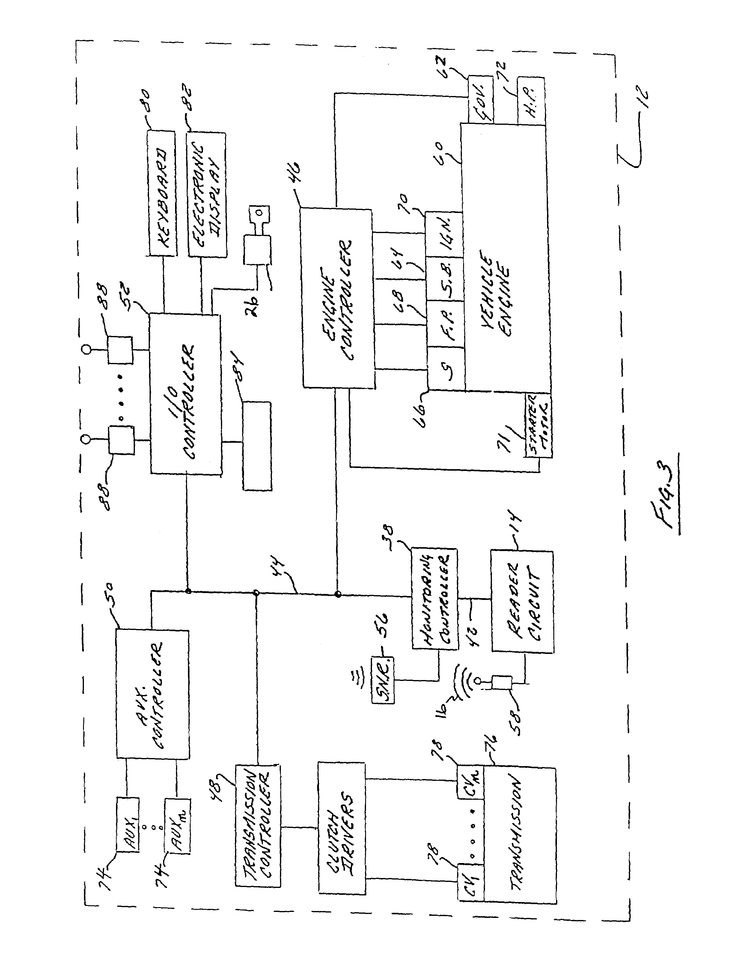
[0024]FIG. 3 shows vehicle control system 12 of FIG. 1 in more detail. Control system 12 includes...


PUM


Abstract

A system and method for controlling access to a work vehicle includes limiting an unauthorized operator's access to the work vehicle by disabling an engine subsystem and additionally limiting access to another vehicle system such as an auxiliary fluid actuator, by disabling at least one of the auxiliary fluid actuators. In this manner, even if a thief hot wires the engine of the work vehicle, he will not be able to use the work vehicle since the engine and the fluid actuators and the fluid controller that controls the actuators are independently disabled.

Description

RELATED APPLICATIONS[0001]This application is a continuation-in-part of U.S. patent application Ser. No. 09 / 752,009 Dec. 28, 2000 which is incorporated herein by reference for all that it teaches, and claims the benefit under Title 35, United States Code, § 120 of that application, insofar as the subject matter of each of the claims of this application is not disclosed in that application in the manner provided by the first paragraph of Title 35, United States Code, § 112.BACKGROUND OF THE INVENTION[0002]Access control or security systems for vehicles, and, in particular, work vehicles, have been provided using a variety of techniques and structures. In a security system in common use in automobiles, an electronic module is inserted between the engine control circuit and the engine to disable certain functions of the engine, such as the spark getting to the spark coil. In simple aftermarket security systems such as the above, it is relatively easy to bypass the security system and s...

Claims


Application Information

Patent Timeline
IPC IPC(8): H04Q9/00E01H8/02E02F3/58G08C19/00B60R25/04G05B19/00G06F7/04G07C9/00H01H47/00
CPCB60R25/04B60R25/24G07C9/00309G07C2209/04B60R2325/105
Inventor DIX, PETER J.
Owner CNH IND AMERICA LLC
Why Eureka
Try Eureka