Linear polarization planar microstrip antenna array with circular patch elements and co-planar annular sector parasitic strips

Active Publication Date: 2006-02-14
DELPHI TECH INC
View PDF7 Cites 14 Cited by
  • Summary
  • Abstract
  • Description
  • Claims
  • Application Information

AI Technical Summary

Benefits of technology

[0004]The present invention is directed to an improved planar microstrip antenna including one or more aperture-fed circular disk patch radiating elements capacitively coupled to respective parasitic strip elements. The circular disk patches are symmetrically disposed above respective ground plane apertures, and the parasitic strip elements are a

Problems solved by technology

However, planar microstrip antennas are inherently limited in input impedance bandwidth, which is a significant disadvantage in variable and wideband frequency applications, and particularly

Method used


Image

  • Linear polarization planar microstrip antenna array with circular patch elements and co-planar annular sector parasitic strips
  • Linear polarization planar microstrip antenna array with circular patch elements and co-planar annular sector parasitic strips
  • Linear polarization planar microstrip antenna array with circular patch elements and co-planar annular sector parasitic strips

Examples


Embodiment Construction

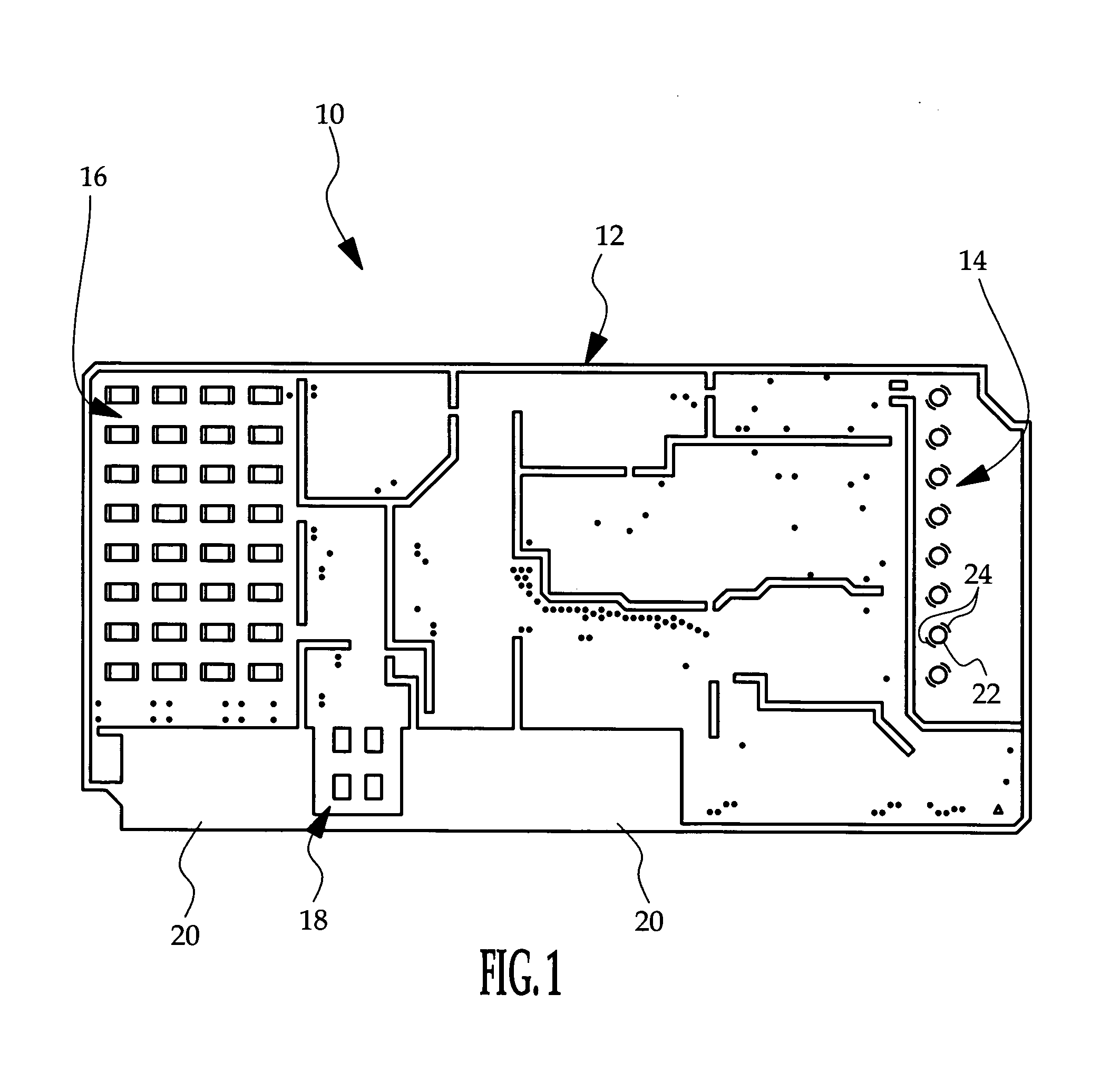
[0008]The present invention is illustrated herein in the context of a radar transceiver 10 designed for radar object detection in a motor vehicle back-up and parking aid. However, it should be understood that the present invention applies to planar microstrip antennas in general, regardless of application.

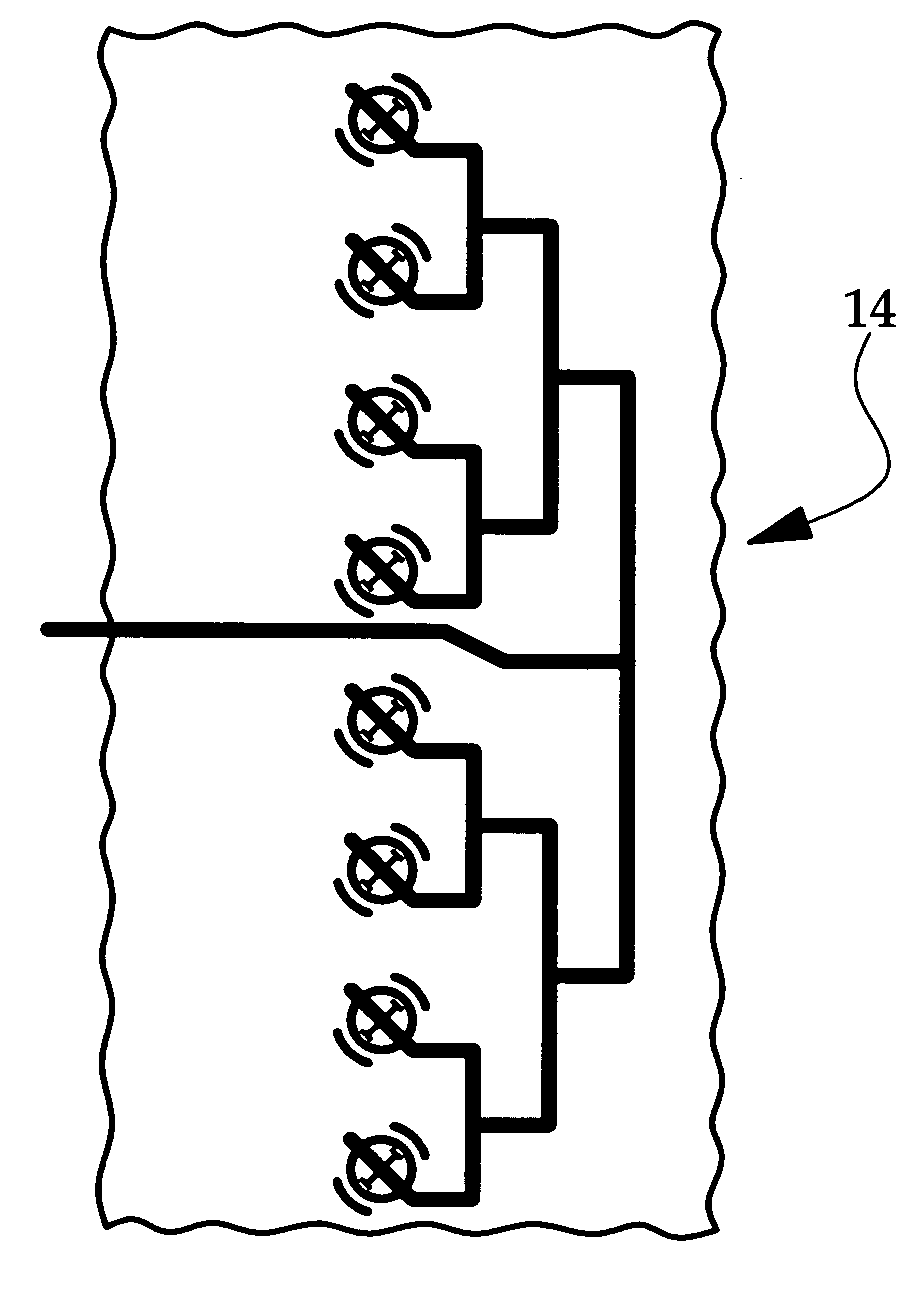
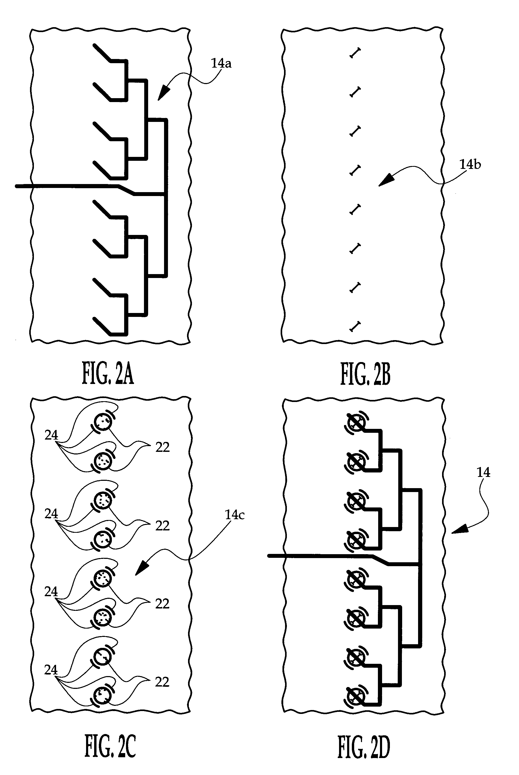
[0009]Referring to FIG. 1, the transceiver 10 is constructed as a populated multi-layer circuit board 12. In usage, the circuit board 12 is mounted in a plastic housing, which in turn, is mounted on a vehicle bumper structure behind a plastic bumper covering or fascia. The field-of-view requirements in object detection applications are typically quite extensive, and are satisfied in the illustrated embodiment by equipping the transceiver 10 with one transmitter antenna 14 and a pair of receiver antennae 16, 18. The transmitter antenna 14 illuminates the entire field-of-view with radar energy; the receiver antenna 16 is responsive to long-range narrow-angle reflected energy, while t...


PUM


Abstract

A planar microstrip antenna includes one or more aperture-fed circular patch radiating elements capacitively coupled to respective parasitic strip elements. The circular patches are symmetrically disposed above respective ground plane apertures, and the parasitic strip elements are annular sectors that are co-planar and concentric with the circular patches, and placed adjacent to the periphery of each circular patch. The disclosed geometry enhances the input impedance bandwidth, and significantly reduces off-boresight radiation variability to provide beam directivity that is more uniform over both frequency and direction.

Description

TECHNICAL FIELD[0001]The present invention relates to a linear polarized planar microstrip radiating antenna element, and more particularly to a circular patch geometry that provides improved antenna element performance.BACKGROUND OF THE INVENTION[0002]Planar microstrip antenna elements and arrays are utilized in a variety of applications due to their simple structure, packaging advantages, and ease in fabrication and integration with associated electronic circuitry. However, planar microstrip antennas are inherently limited in input impedance bandwidth, which is a significant disadvantage in variable and wideband frequency applications, and particularly in spread-spectrum applications.[0003]It is known that the input impedance bandwidth of planar microstrip antenna elements and arrays can be improved by aperture feeding the radiating elements. This can be accomplished by constructing the antenna element or array as a set of three vertically aligned metal layers separated by interve...

Claims


Application Information

Patent Timeline
IPC IPC(8): H01Q1/38
CPCH01Q1/38H01Q21/065H01Q19/005H01Q9/0407
Inventor MATEYCHUK, DUANE E.
Owner DELPHI TECH INC
Why Eureka
Try Eureka