
Mobile radiographic apparatus, radiographic system, radiographic method, program, computer-readable storage medium, and information system

a mobile radiographic and radiographic technology, applied in electrical devices, medical science, diagnostics, etc., can solve the problems of poor input/output efficiency, poor reliability, and inability to connect to any information system in the hospital, and achieve the effect of effective work flow and efficient operation

Inactive Publication Date: 2006-02-14
CANON KK
View PDF25 Cites 30 Cited by
  • Summary
  • Abstract
  • Description
  • Claims
  • Application Information

AI Technical Summary

Benefits of technology

[0020]The present invention has been made to solve the above problems, and has an object to realize

Problems solved by technology

However, the mobile X-ray imaging apparatus is not connected to any information system in the hospital.
According to the film / screen method, since no image is digitalized, both the stationary and mobile X-ray imaging apparatuses are not generally connected to the network in a hospital.
The conventional operation based on documents has posed problems in terms of poor input / output efficiency and poor reliability related to errors in writing, posting errors, and the like.
In addition, since each technician determined an imaging order, he / she did not always follow the most efficient, shortest route, resulting in poor imaging efficiency.
When an X-ray detection sensor is to be used for a mobile X-ray imaging apparatus, since a control device and image storage device for the X-ray detection sensor are incorporated in the mobile X-ray imaging apparatus, the operation efficiency becomes very poor unless the apparatus has some means for connecting to the network in the hospital.
The operation time may undesirably become long or a data entry error may occur.
In addition, since there has been no system for determining an imaging order, the imaging efficiency has been poor.

Method used


Image

  • Mobile radiographic apparatus, radiographic system, radiographic method, program, computer-readable storage medium, and information system
  • Mobile radiographic apparatus, radiographic system, radiographic method, program, computer-readable storage medium, and information system
  • Mobile radiographic apparatus, radiographic system, radiographic method, program, computer-readable storage medium, and information system

Examples


first embodiment

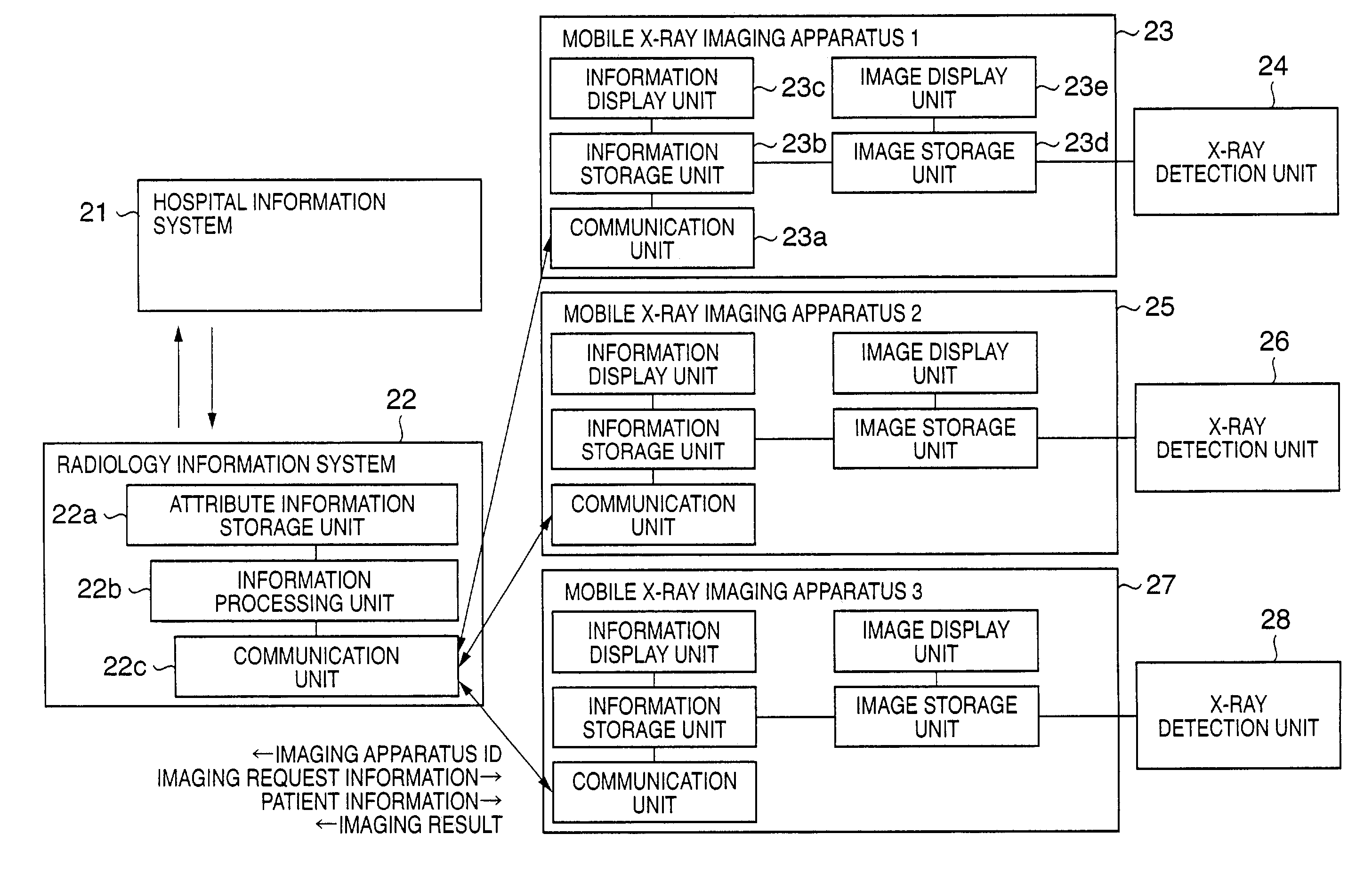
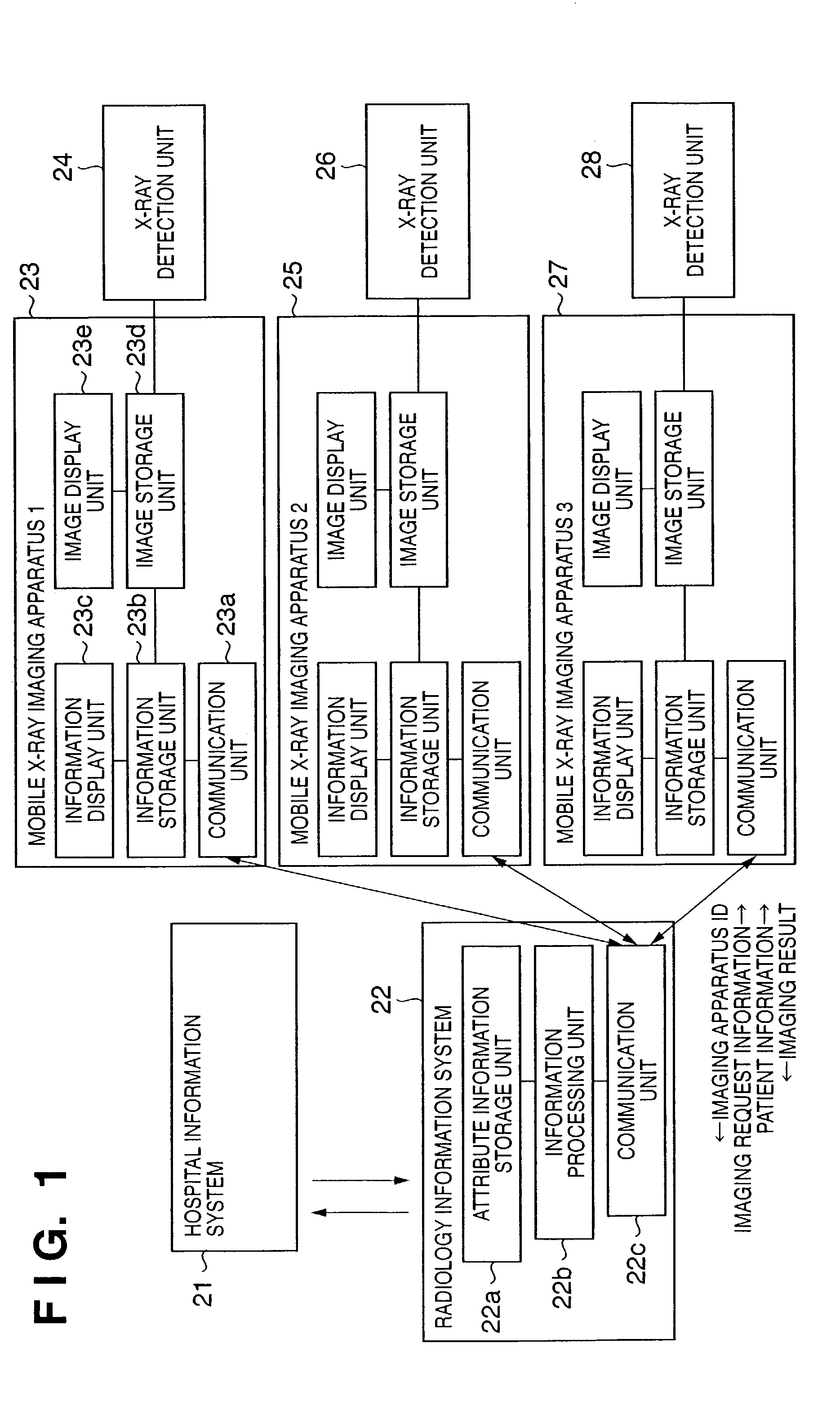
[0040]FIG. 1 is a block diagram showing the schematic arrangement of an X-ray imaging system according to the present invention.

[0041]Referring to FIG. 1, reference numeral 21 denotes a hospital information system; 22, a radiology information system; 23, 25, and 27, first, second, and third mobile X-ray imaging apparatuses; and 24, 26, and 28, X-ray detection units respectively included in the mobile X-ray imaging apparatuses 23, 25, and 27. The mobile X-ray imaging apparatuses 23, 25, and 27 have the same arrangement. The following description will be made by using the mobile X-ray imaging apparatus 23 as a typical example.

[0042]As described above, the hospital information system 21 handles overall in-hospital management information such as patient information (e.g., patient IDs, patient names, sexes, and dates of birth) and accounting information. Likewise, the radiology information system 22 manages imaging request information concerning imaging operation, e.g., receiving an imag...

second embodiment

[0061]FIG. 3 is a block diagram showing the schematic arrangement of an X-ray imaging system according to the present invention.

[0062]Note that the same reference numerals as in FIG. 1 in the first embodiment denote the same parts in FIG. 3. The second embodiment differs from the first embodiment in that a communication unit 33a of a mobile X-ray imaging apparatus 33 can communicate with a communication unit 31a installed in a hospital information system 31 as well as a communication unit 32c of a radiology information system 32. Units 32a, 32b, 33b, 33c, 33d, and 33e in FIG. 3 respectively have the same functions as those of the units 22a, 22b, 23b, 23c, 23d, and 23e in FIG. 1.

[0063]According to the second embodiment having this arrangement, the mobile X-ray imaging apparatus 33 and mobile X-ray imaging apparatuses 35 and 37 each can receive patient information from the hospital information system 31 by transmitting, to the hospital information system 31, the patient ID of a patien...

third embodiment

[0065]FIG. 4 is a block diagram showing the schematic arrangement of an X-ray imaging system according to the present invention.

[0066]Note that the same reference numerals as in FIG. 1 in the first embodiment denote the same parts in FIG. 4. The third embodiment differs from the second embodiment in that the attribute information storage unit 22a incorporated in the radiology information system 22 is incorporated as an attribute information storage unit 43f in each of mobile X-ray imaging apparatuses 43, 45, and 47. Units 42b, 42c, 43a, 43b, 43c, 43d, and 43e in FIG. 4 respectively have the same functions as those of the units 22b, 22c, 23a, 23b, 23c, 23d, and 23e in FIG. 1.

[0067]According to the third embodiment having this arrangement, since the attribute information storage unit 43f is incorporated in each mobile X-ray imaging apparatus, the operator (X-ray imaging technician) can easily change attribute information. This allows the operator to quickly cope with a case wherein, f...


PUM


Abstract

In a radiographic method using a mobile radiographic apparatus including an image generating unit which includes photoelectric conversion elements and generates radiographic image data of an object, key information for selecting radiographic request information is transmitted to an external information system having the radiographic request information. The radiographic request information transmitted from the information system is received. The operation of the image generating unit is controlled based on the received radiographic request information.

Description

FIELD OF THE INVENTION[0001]The present invention relates to radiography using a mobile radiographic apparatus.BACKGROUND OF THE INVENTION[0002]Conventionally, as the commonest imaging method for X-ray imaging, the film / screen method has been used. In this method, imaging is performed by using a combination of a light-sensitive film and a phosphor having sensitivity to X-rays. Phosphors made of a rare-earth material that emits light upon being irradiated with X-rays are held in tight contact with the two surfaces of a light-sensitive film. X-rays transmitted through an object to be imaged are converted into visible light by the phosphors, and the light is captured by the light-sensitive film. The latent image formed on the light-sensitive film is developed by a chemical treatment, thereby visualizing the image.[0003]As the second imaging method, a method called the computed radiography (CR) method has also been put into practice. In this method, a radiation transmission image is tem...

Claims


Application Information

Patent Timeline
IPC IPC(8): H05G1/10A61B6/00
CPCA61B6/4233A61B6/4405A61B6/4494A61B6/56A61B6/563A61B6/464A61B6/00
Inventor OKODA, KEIJI
Owner CANON KK
Learn More