Buffer controller and management method thereof

a buffer controller and buffer controller technology, applied in the direction of data conversion, memory adressing/allocation/relocation, instruments, etc., can solve the problems of low execution efficiency and heavy sdram load, and achieve the effect of saving memory space and facilitating efficient use of buffer memory

Active Publication Date: 2006-02-14
VIA TECH INC
View PDF6 Cites 5 Cited by
  • Summary
  • Abstract
  • Description
  • Claims
  • Application Information

AI Technical Summary

Benefits of technology

[0007]An object of the present invention is to provide a buffer controller, which uses a new link structure to manage the allocation and release of buffer registers, thereby improving the buffer memory access efficiency and simplifying the hardware design.
[0009]In another embodiment of the present invention, a new linked structure is applied to the allocation action of the buffer controller, so that the released segment can immediately obtain the information of the second address without the report to the buffer controller. The linked structure has a first buffer register to directly point to the last buffer register, then the last buffer register points to the second buffer register. The linked structure from the second buffer register to the last buffer register is a list structure. Therefore, the release of buffer memory can immediately obtain the information about the second address from the link node of the last buffer register. The second address is stored in the link node of the buffer register pointed by the tail pointer, then the last address is stored in the tail pointer. Therefore, the segment with the linked structure can be directly linked to the end of an unused list without releasing one by one. This method does not only save memory space to store the second address, it also retain the original hardware design so that the buffer memory can be used efficiently.

Problems solved by technology

In view of the fact that the conventional buffer management technique involves complicated hardware operations when releasing the used segment according to the conventional linked list, the execution efficiency is low and the SDRAM load is too heavy.

Method used


Image

  • Buffer controller and management method thereof
  • Buffer controller and management method thereof
  • Buffer controller and management method thereof

Examples


first embodiment

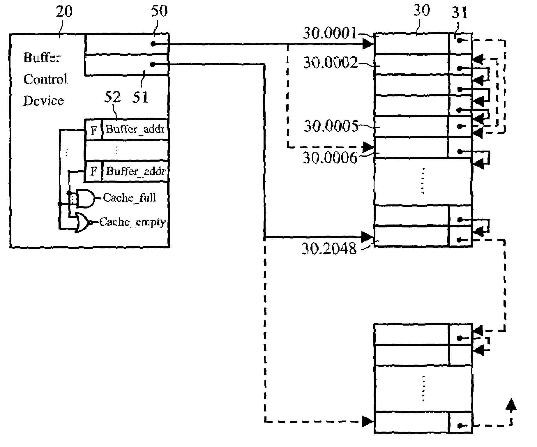
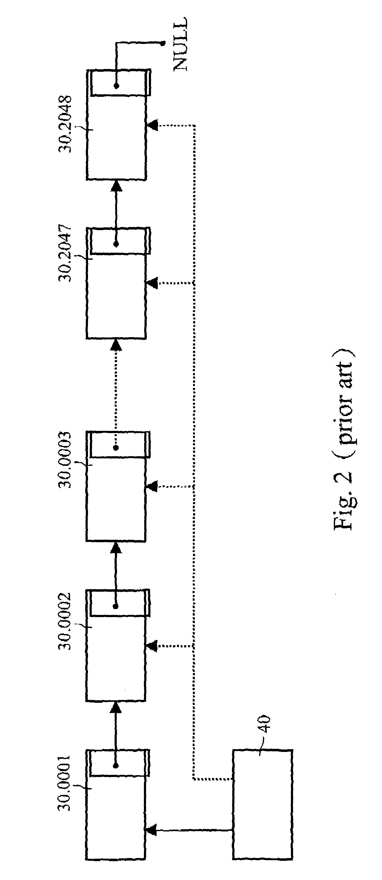
[0018]In the invention, a switch controller uses a buffer controller. The buffer controller controls a buffer memory to temporarily store packets of transmitting data. The buffer controller 20 has a head pointer 50 and a tail pointer 51. After initialization, the pointers 50, 51 point to the first address 30.0001 and the last address 30.2048 of a free list, respectively. Preferably, the buffer controller 20 contains a cache memory 52 for pointing to available buffer registers, so cache memory 52 stores the addresses of available buffer registers. In the free list, the buffer register 30.0001 uses its link node to point to the next buffer register 30.0002; the buffer register 30.0002 uses its link node to point to the next buffer register 30.0003. Such links continue until the last buffer register 30.2048. The link node of the last buffer register 30.2048 points to null, indicating the end of the free list.

second embodiment

[0019]In the invention, suppose the cache memory 52 embedded in the buffer controller of the switch controller has three cache units. These cache units can be embedded SRAM units, flip-flops, or registers. When the switch controller is initialized, the addresses 30.0001, 30.0002, 30.0003 are stored in the cache memory 52 and the head pointer 50 points to the address 30.0004. When allocating a memory space, the addresses of available buffer registers are assigned for the allocation from the cache memory 52 with a priority. As previously planned, each buffer register thus obtained has a size of 128 bytes. If the incoming packets are small ones (the smallest has 64 bytes), the system only needs to ask the cache memory 52 for allocating one buffer register. After using the buffer register, the address of the buffer register released will be stored in the cache memory 52. In this case, the head pointer 50 is rarely used. This means that the number of SRAM access actions is effectively re...


PUM


Abstract

The invention provides a new linked structure for a buffer controller and management method thereof. The allocation and release actions of buffer memory can be more effectively processed when the buffer controller processes data packets. The linked structure enables the link node of the first buffer register to point to the last buffer register. The link node of the last buffer register points to the second buffer register. Each of the link nodes of the rest buffers points to the next buffer register in order until the last buffer register. This structure can effectively release the buffer registers in the used linked list to a free list.

Description

BACKGROUND OF THE INVENTION[0001]1. Field of Invention[0002]The invention relates to a buffer controller and management method thereof. More explicitly, the invention provides a buffer controller that utilizes a new linked structure to manage the allocation and release of a buffer memory and the corresponding buffer management method.[0003]2. Related Art[0004]With reference to FIG. 1, normally a buffer memory 30 is installed between a controller and other devices for temporarily storing and managing data. The buffer memory 30 can be an SDRAM (Synchronous Dynamical Random Access Memory), an SRAM (Static Random Access Memory), or a DRAM (Dynamical Random Access Memory). The controller 10 and the buffer memory 30 are further connected with a buffer controller 20 in between. The buffer controller 20 is used to manage data access between the controller 10 and the buffer memory 30 to increase the data processing efficiency.[0005]FIG. 2 is a schematic view of conventional buffer management...

Claims


Application Information

Patent Timeline
Patent Type & Authority Patents(United States)
IPC IPC(8): G06F12/02G06F5/10
CPCG06F5/10G06F12/023G06F2205/106
Inventor CHEN, MURPHYHU, PERLMAN
Owner VIA TECH INC
Why Eureka
Try Eureka