Wheel speed sensor, method for producing the same, terminal and method for welding terminal and electric wire

a technology of speed sensor and terminal, applied in the direction of acceleration measurement using interia force, galvano-magnetic hall-effect devices, instruments, etc., can solve the problems of sensor damage, number of man hours required to assemble the respective constituent parts, and liable disconnecting of the connecting portion between the lead portion and the electric wir

Inactive Publication Date: 2006-02-21
NISSIN KOGYO CO LTD
View PDF22 Cites 10 Cited by
  • Summary
  • Abstract
  • Description
  • Claims
  • Application Information

AI Technical Summary

Benefits of technology

[0040]The invention was made with a view to solving the problems, and an object thereof is to provide a wheel speed sensor which enables the assemblage of respective component parts with fewer man hours in sealing the wheel speed sensor wi

Problems solved by technology

However, in the event that the magnetic sensors such as Hall ICs are provided directly on the axle portions of the running vehicle, there is a risk that the sensors maybe damagedby flying stones, and moreover, a connecting portion between lead portions and electric wires is liable to be disconnected.
As has been described heretofore, in the conventional wheel speed sensor, the electric wires have to be connected to the terminals of the detection element by welding or clamping, the detection element to which the electric wires are connected has to be accommodated in the accommodating portion, and the lid unit has to be mounted on the accommodating portion prior to sealing with the resin, this causing a problem that a number of man hours are required to assemble the respective constituent component parts.
In addition, in this construction in which the detection element is accommodated in the accommodating portion for sealing with the resin after the electric wires have been connected to the terminals of the detection element, stress is applied to the terminals and the electric wires before they are accommodated in the accommodating portion, and this may trigger a risk that the connection between the detection element and the electric wires is disconnected.
Due to this, the posture and position of the assembly within the cavity tend to remain unstable until the assembly is clamped by the mold halves.
Since the assembly is placed in the cavity while the electric wires are connected to the assembly with an L-shape, the assembly is liable to be twisted or floated within the cavity.
When there is caused a deviation in position of the assembly within the cavity, it is not possible to form a uniform resin sealed portion, whereby the penetration of water or the like into the assembly from an exposed portio

Method used


Image

  • Wheel speed sensor, method for producing the same, terminal and method for welding terminal and electric wire
  • Wheel speed sensor, method for producing the same, terminal and method for welding terminal and electric wire
  • Wheel speed sensor, method for producing the same, terminal and method for welding terminal and electric wire

Examples


Embodiment Construction

[0059]A preferred embodiment of the invention will be described below with reference to the accompanying drawings.

[0060]The embodiment will describe a wheel speed sensor for use in detecting wheel speeds of vehicles such as automobiles and motorcycles and a method for producing the same wheel speed sensor with reference to the accompanying drawings.

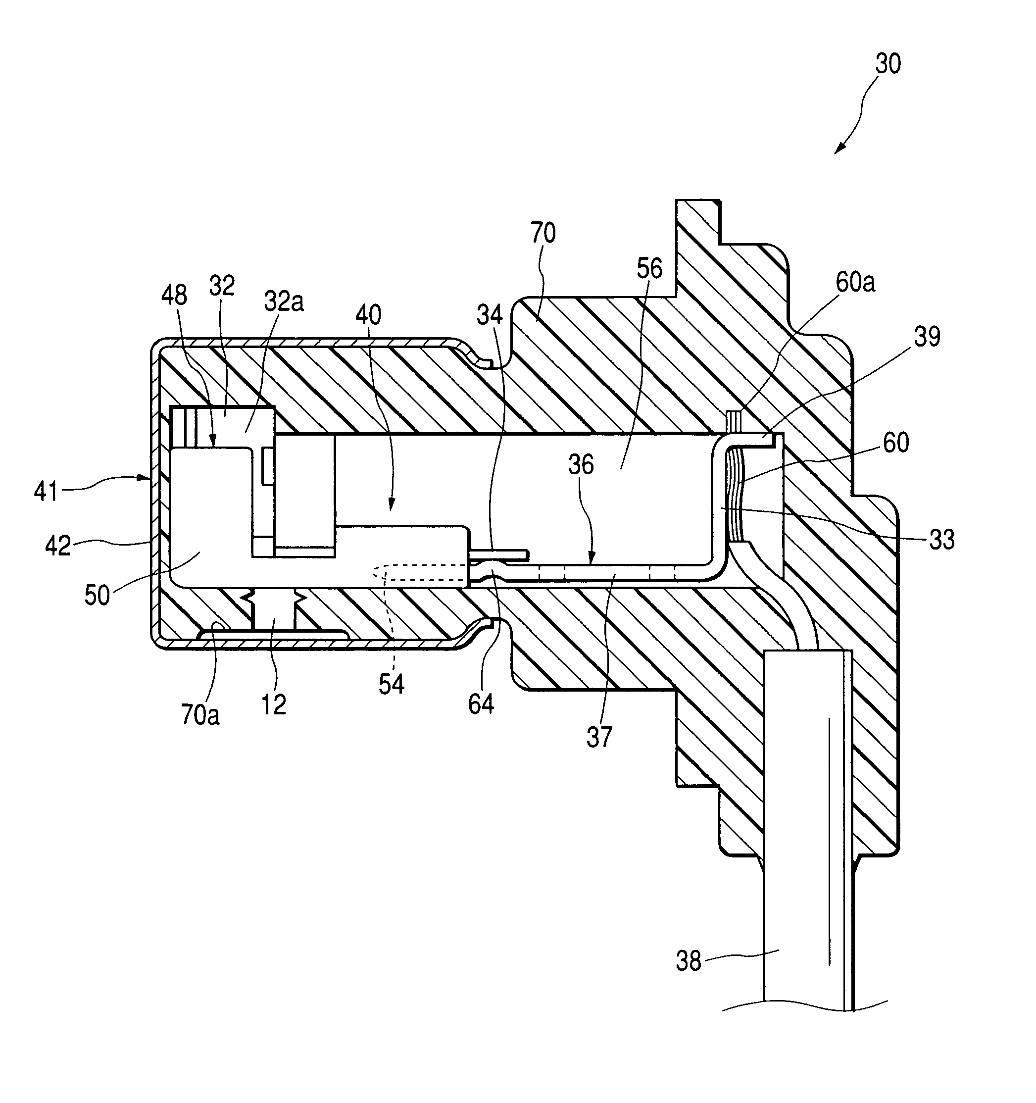
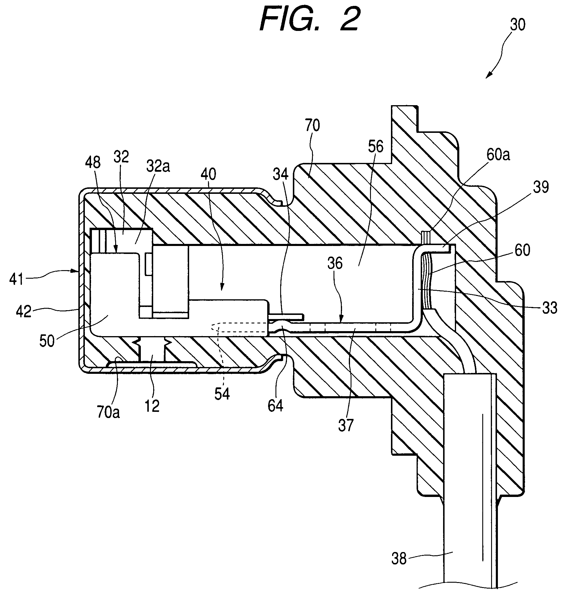
[0061]Referring to FIGS. 1 to 5C, the construction of the wheel speed sensor will be described.

[0062]In FIG. 1, a wheel speed sensor 30 is provided together with a brake system provided on each wheel of a vehicle and is disposed in such a manner as to confront a rotor of a magnetic material (not shown). The wheel speed sensor 30 is designed to detect the speed of the wheel using a detection element (a Hall IC or a MR element). The detection element is adapted to detect a change in voltage associated with a change in magnetic flux which occurs when irregularities or slit holes formed in the rotor pass through the detection element.

[0063]Th...


PUM

PropertyMeasurementUnit
Diameteraaaaaaaaaa
Speedaaaaaaaaaa

Abstract

A wheel speed sensor has a detection element having at least one lead for detecting a wheel speed, at least one terminal portion connected to the lead of the detection element, a holder portion having a detection element fitting portion fitting the detection element therein and a terminal portion fitting portion fitting the terminal portion therein, and a resin sealed portion sealing the holder portion in a state the detection element and the terminal portion connected with an electric wire are held in the holder portion. The detection element fitting portion and the terminal portion fitting portion are disposed such that the lead of the detection element is brought into abutment with or proximity to a predetermined location of the terminal portion when the detection element and the terminal portion are fitted in the detection element fitting portion and the terminal portion fitting portion, respectively.

Description

CROSS REFERENCE TO RELATED APPLICATIONS[0001]This application is a divisional application of co-pending U.S. patent application Ser. No. 10 / 214,154 filed Aug. 8, 2002 now U.S. Pat. No. 6,759,594, which is now incorporated herein by reference.BACKGROUND OF THE INVENTION[0002]1. Field of the Invention[0003]The present invention relates to a wheel speed sensor for use in detecting wheel speeds of vehicles such as automobiles and motorcycles. Further, the present invention relates to a terminal to which an electric wire is connected in which a plurality of thin metallic wires are bundled together to constitute a conducting portion and a method for welding the electric wire to the terminal.[0004]2. Description of the Related Art[0005]In general, wheel speed sensors attached to wheels of a vehicle, respectively, to detect wheel speeds of a running vehicle are designed to detect the rotation of rotors which rotate together with axles coupled to the respective wheels. The rotors contain a m...

Claims


Application Information

Patent Timeline
IPC IPC(8): G01P1/02G01P3/42
CPCG01P1/026Y10T29/49179
Inventor IIJIMA, JUNOTA, KAZUHIROFUKAZAWA, SHIGERU
Owner NISSIN KOGYO CO LTD
Why Eureka
Try Eureka