Adjustable valve for variable flows and a method for reducing flow through a valve

a variable flow, valve technology, applied in the field of valves for variable flows, can solve the problems of unsatisfactory requirements, increased energy costs, and unnecessary energy consumption, and achieve the effect of quiet operation and small power consumption

Inactive Publication Date: 2006-02-21
LINDINVENT
View PDF19 Cites 30 Cited by
  • Summary
  • Abstract
  • Description
  • Claims
  • Application Information

AI Technical Summary

Benefits of technology

[0024]An advantage with the valve according to this embodiment is that it needs very small actuator forces, since the element which is moved upon opening and closing of the valve is a tube member with open ends which is displaced in its axial direction. Thereby the air pr

Problems solved by technology

These ventilation systems therefor cause unnecessary consumption of energy and raised energy costs.
Among the ventilation systems known today there is no system capable of meeting the requirements above.
When reducing the air-flow in these systems a significant pressure difference occurs over a very short distance at the edge of the plate, which gives rise to a considerable amount of turbulence, i.e. a powerful sound is generated over the edge of the plate.
Furthermore, a throttle damper cannot reduce the air-flow efficiently since there will be a small open gap between the plate and the housing of the damper even in a closed state.
There are throttle dampers arranged with a rubber sealing but these are not advantageous to use since they demand actuators with high torque.
This is a problem for instance in certain conference installations were conference participants placed in the vicinity of the ventilation device experience that cold air is blown upon them, whereas participants located at a distance from the device will not experience any ventilation at all.
The need for cooling work facilities has increased enormously during recent years, which has led to the repeated braking of energy consumption records during the summer months.
These solutions demand that a supply system for a circulating cooling medium is arranged in the facility, which is both energy demanding and brings about a high investment cost.
Because of these difficulties in the prior art to cope with these demands, it has only been possible to supply input air which is a few degrees cooler than the ambient room temper

Method used


Image

  • Adjustable valve for variable flows and a method for reducing flow through a valve
  • Adjustable valve for variable flows and a method for reducing flow through a valve
  • Adjustable valve for variable flows and a method for reducing flow through a valve

Examples


Embodiment Construction

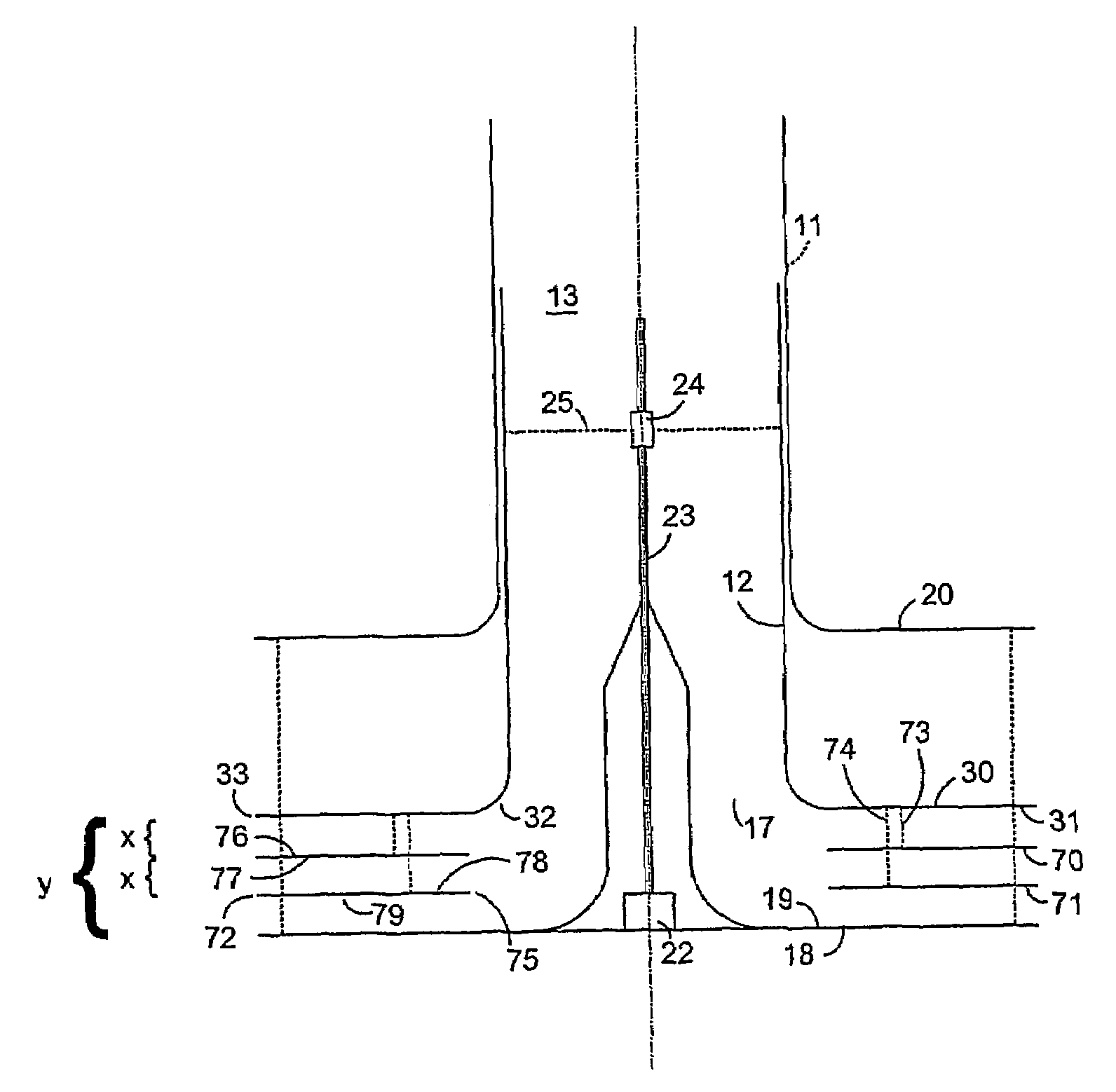
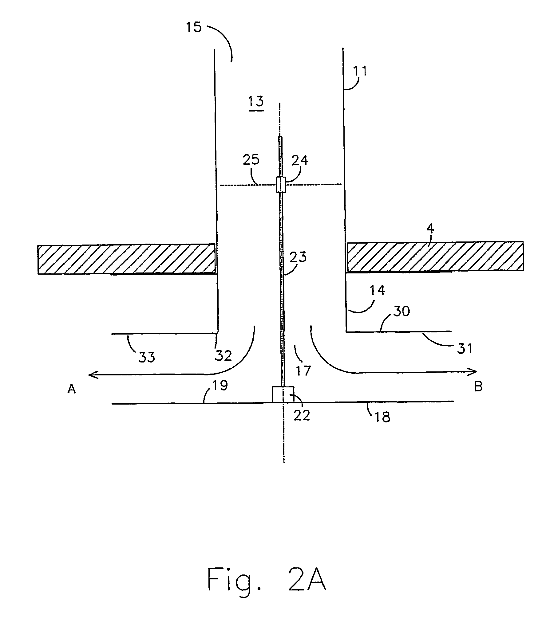
[0037]The present invention relates to a valve for variable air flows which is capable of reducing the air-flow with minimum sound generation.

[0038]In FIG. 2A a valve according to the present invention is shown, comprising a tube 11 arranged e.g. at the ceiling 4 of a room, which tube 11 forms a conduit 13 for flow of air. The tube comprises a first stationary tube member 11, preferably firmly arranged towards said ceiling 4 at the first open end 14 of the tube member. The stationary tube member has an open output opening 17 at the first end 14. An open input opening 15 is arranged at the second end of the tube member 11, arranged for connection to a ventilation system (not shown) for supply of air. Hence, the valve is devised for flow of air from said input end 15, through the conduit 13, and out through said output opening 17. Furthermore, the valve comprises a flow reducing device 18 for regulation of the air flow out from the tube 11. Said flow reducing device 18 displays a surf...


PUM


Abstract

A fluid valve comprises a fluid conduit and a flow reducing device. The fluid conduit includes a fluid input end and a fluid output end. The flow reducing device comprises a first fluid passage and is configured to adjust the width of the first fluid passage. The first fluid passage has a narrow width over an extended flow distance that is delimited by internal walls that cause a pressure gradient in fluid passing through the first fluid passage. The flow reducing device further comprises a second fluid passage having a narrow width over an extended flow distance that is delimited by internal walls. The first fluid passage and the second fluid passage are parallel to each other. The flow reducing device further comprises a plurality of damping elements having surface portions parallel to each other. The facing surface portions of adjacent pairs of said damping elements define the internal walls delimiting the first and second fluid passages.

Description

RELATED APPLICATIONS[0001]The present application is a 35 U.S.C. §371 national phase application of PCT International Application No. PCT / SE01 / 02359, having an international filing date of Oct. 26, 2001, and claiming priority to Sweden Patent Application No. 0003886-9, filed Oct. 26, 2000, and Sweden Patent Application No. 0004146-7, filed Nov. 14, 2000, the disclosures of which are incorporated herein by reference in their entireties. The above PCT International Application was published in the English language and has International Publication No. WO 02 / 35157 A1.FIELD OF THE INVENTION[0002]The present invention relates to a valve for variable flows, and particularly to a valve adapted to provide air-flows within a wide flow range, with limited generation of noise.BACKGROUND[0003]Many properties, for instance private houses and offices, are today devised with built-in ventilation systems in order to provide a better in-door climate for the residents and employees. In many present v...

Claims


Application Information

Patent Timeline
IPC IPC(8): F16K31/00F16K1/12
CPCF16K1/123Y10T137/86734Y10T137/86759
Inventor LINDBORG, HERMAN
Owner LINDINVENT
Why Eureka
Try Eureka