Shrouded turbine blades with locally increased contact faces

a turbine blade and local increase technology, applied in the direction of propellers, propulsive elements, water-acting propulsive elements, etc., can solve the problems of increased shroud weight, cost and reliability problems, and inability to meet the needs of use, so as to reduce the stress of face contact and reduce the stress of conta

Inactive Publication Date: 2006-02-21
PRATT & WHITNEY CANADA CORP
View PDF16 Cites 51 Cited by
  • Summary
  • Abstract
  • Description
  • Claims
  • Application Information

AI Technical Summary

Benefits of technology

[0007]It is an object of the present invention to provide a shrouded turbine blade having improved contact wear performance. The invention lowers contact stresses and thereby provides, among other things, a design which is less sensitive to shroud misalignment due to shroud wear, deflection or tolerance stack-up at assembly.
[0009]There is also provided, in accordance with the present invention, a blade for a turbine section of a gas turbine engine, the blade comprising: an airfoil portion extending from a root portion to a tip portion; and a shroud portion extending laterally from the airfoil portion, the shroud portion having a body portion having a substantially constant thickness and a pair of opposed bearing faces each having contact portions adapted to matingly contact a bearing face contact portion of a shroud portion of an adjacent turbine blade, wherein the body portion is generally planar and has an increase in thickness immediately adjacent the contact portion of at least one of the opposed bearing faces to thereby provide substantially all of the contact portion of said bearing face with an increased surface area associated with said increased thickness, and wherein said increased surface area is adapted to lower contact stresses arising from contact with at least one mating bearing face of said adjacent turbine blades.
[0010]There is further provided, in accordance with the present invention, a method of reducing face contact stress in a shroud contact face of a shrouded turbine blade, the method comprising the steps of: determining a desired shroud design for a given turbine blade design, the shroud design including a nominal thickness; determining a desired face contact stress for at least one shroud contact face of the shroud, the at least one shroud contact face having a contact portion length; and providing a local increase in the shroud nominal thickness to thereby increase the area of the at least one shroud contact face along said contact portion length, wherein the increase in area corresponds to the desired face contract stress, and wherein the local increase is limited to a region immediately adjacent the at least one shroud contact face.

Problems solved by technology

Numerous problems face the designer of a shrouded gas turbine blade as a result of the high heat and high speed environment in which the shrouded blade must operate.
And, as if these design problem were not enough, in airborne applications excess weight in itself is also a penalty.
These features, however, come at the price of increases in shroud weight.
In use, fretting can occur on contract surfaces of abutting turbine shrouds, which is of course undesirable.
While perhaps effective, these solutions introduce manufacturing steps and materials, and therefore cost and reliability issues as well.

Method used


Image

  • Shrouded turbine blades with locally increased contact faces
  • Shrouded turbine blades with locally increased contact faces
  • Shrouded turbine blades with locally increased contact faces

Examples


Embodiment Construction

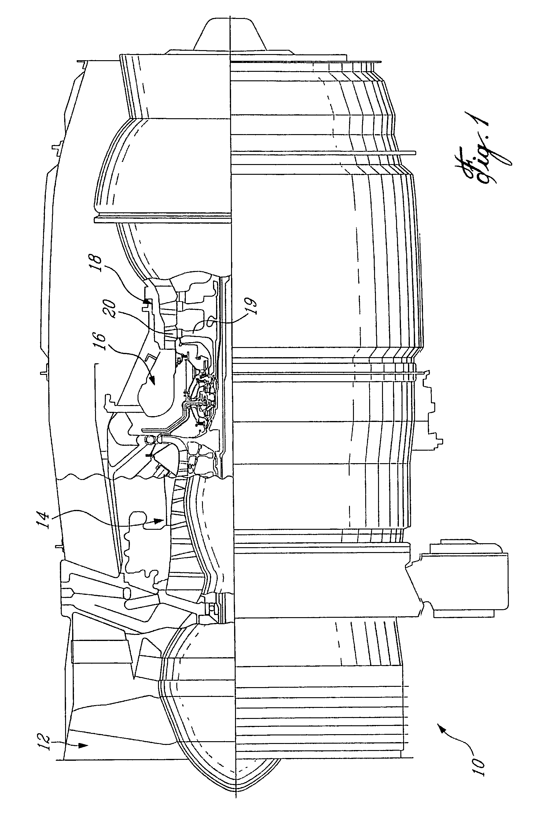
[0020]FIG. 1 schematically illustrates a gas turbine engine 10 (a turbofan in this case, though the invention may be practised in almost any gas turbine engine) generally comprising, in serial flow communication, a fan 12 through which ambient air is propelled, a multistage compressor 14 for pressurizing the air, a combustor 16 in which the compressed air is mixed with fuel and ignited for generating an annular stream of hot combustion gases, and a turbine section 18 for extracting energy from the combustion gases. The turbine section comprises at least one turbine rotor 19, having a plurality of radially extending turbine blades 20 in accordance with the present invention.

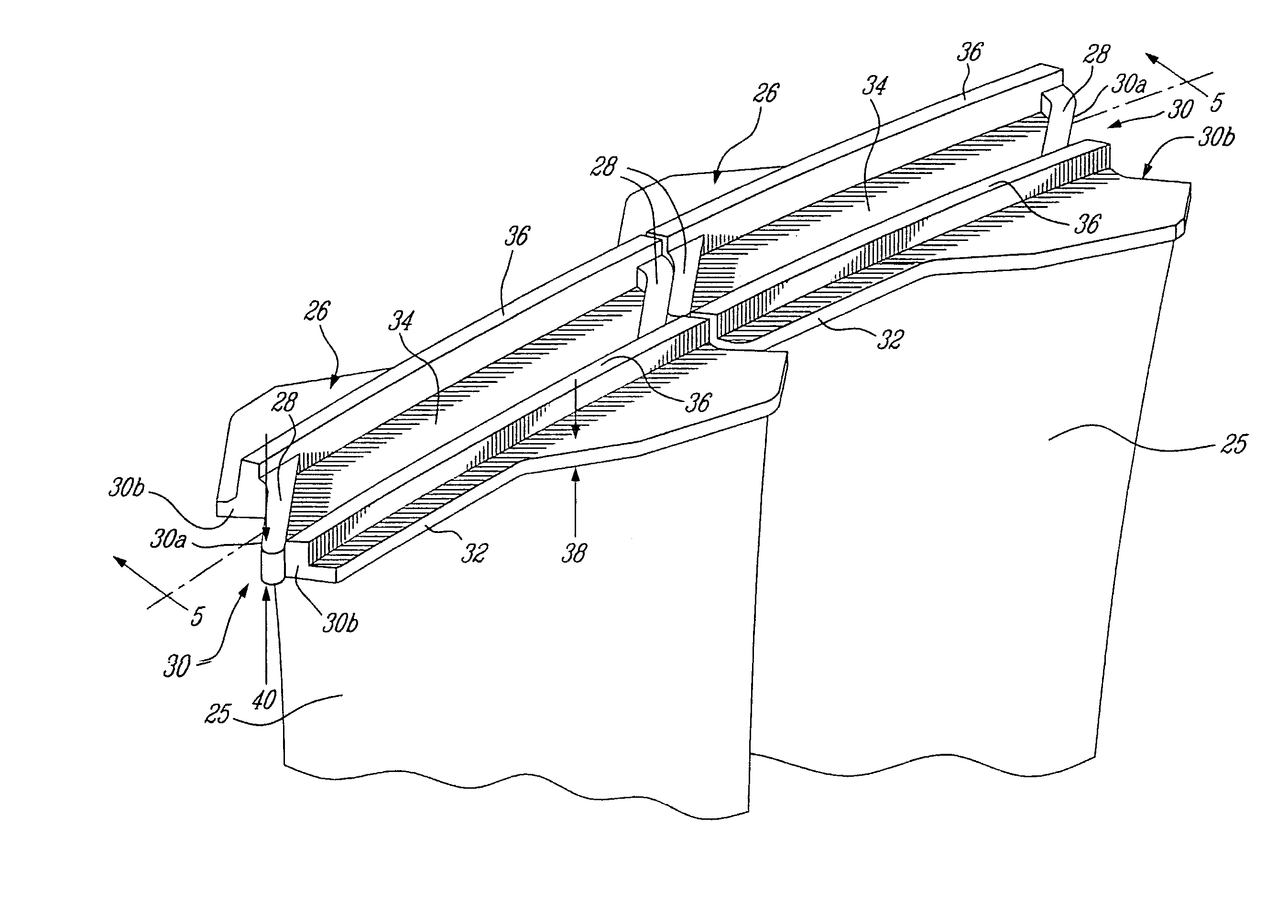
[0021]FIG. 2 depicts a tip portion of a prior art shrouded turbine blade 90, which comprises an airfoil section 91 and a shroud 92. The shroud 92 has a thickness defining opposed bearing or contact faces 93, which are shaped to facilitate interlocking of adjacent shrouds. Shroud 92 includes stiffening rails 94, wh...


PUM

PropertyMeasurementUnit
thicknessaaaaaaaaaa
angleaaaaaaaaaa
surface areaaaaaaaaaaa

Abstract

A one-piece blade for a turbine section of a gas turbine engine, the blade comprising a root, an airfoil and a shroud. The shroud extends generally perpendicularly from a tip of the airfoil and is defined by a pair of opposed bearing faces and a pair of opposed non-bearing faces. The bearing faces each have a contact portion adapted to contact a shroud of an adjacent blade. The shroud has a substantially constant nominal thickness and the bearing faces have a substantially constant face thickness across the contact portion, the face thickness being greater than the nominal thickness. The transition between the face thickness and the nominal thickness is substantially discontinuous.

Description

TECHNICAL FIELD[0001]The present invention relates generally gas turbine engines, and more particularly to shrouded turbine blades therefor.BACKGROUND OF THE INVENTION[0002]Numerous problems face the designer of a shrouded gas turbine blade as a result of the high heat and high speed environment in which the shrouded blade must operate. Vibration damping, creep curling, bending stresses, contact stress wear, shroud misalignment and dynamic effects are just a few of the demons facing the designer. And, as if these design problem were not enough, in airborne applications excess weight in itself is also a penalty.[0003]Much attention has been paid in the prior art to improving the damping and bending strength of shrouded blades. However, one area where further improvement is needed is the reduction of contact-related wear between adjacent shrouded blades.[0004]A shrouded rotor blade assembly typically comprises a plurality of airfoil blades extending radially from a rotor having a cent...

Claims


Application Information

Patent Timeline
Patent Type & Authority Patents(United States)
IPC IPC(8): F01D5/22F01D5/20
CPCF01D5/225Y10T29/49321Y10T29/49336
Inventor PAQUET, RENEGRIVAS, NICOLASBRANDT, RICHARD
Owner PRATT & WHITNEY CANADA CORP
Why Eureka
Try Eureka