Structure of an air inflation device

Inactive Publication Date: 2006-02-21
CHEN CHIH MING
View PDF10 Cites 7 Cited by
  • Summary
  • Abstract
  • Description
  • Claims
  • Application Information

AI Technical Summary

Benefits of technology

[0007]Another object of the present invention is to provide an improved structure of an inflation device, wherein the device is provided with excellent heat dissipation so that the excessive heat caused the burning of th

Problems solved by technology

However, the heat dissipated by the motor in the course of operation has affected seriously the efficiency of the motor.
In other words, this conventional air inflation device has a very short live of use.
Besides, in the course of op

Method used


Image

  • Structure of an air inflation device
  • Structure of an air inflation device
  • Structure of an air inflation device

Examples


Example

[0021]The following descriptions are of exemplary embodiments only, and are not intended to limit the scope, applicability or configuration of the invention in any way. Rather, the following description provides a convenient illustration for implementing exemplary embodiments of the invention. Various changes to the described embodiments may be made in the function and arrangement of the elements described without departing from the scope of the invention as set forth in the appended claims.

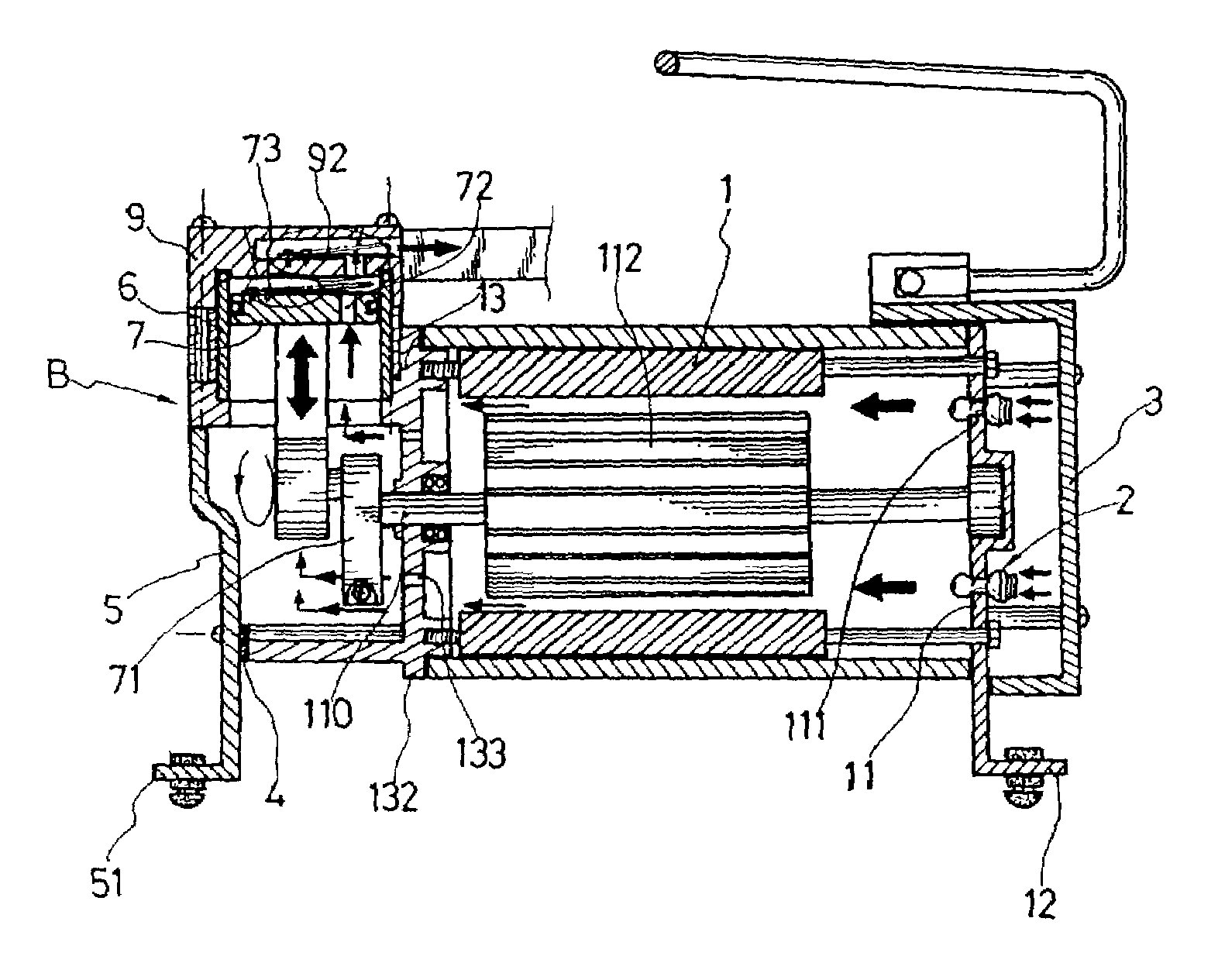
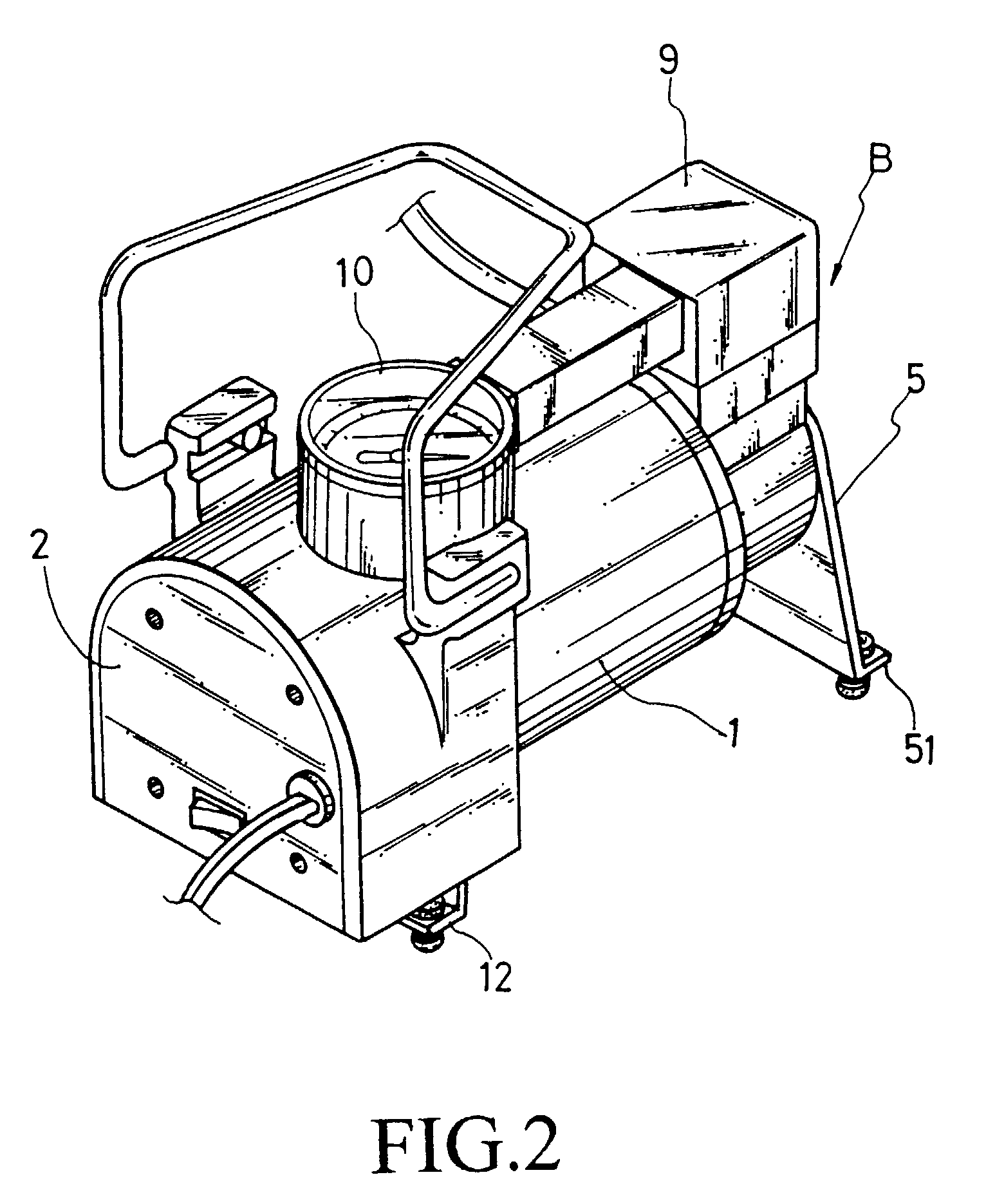
[0022]Referring to FIGS. 2 and 3 there is shown an improved structure of an air inflation device comprising a motor 1, a mini-sized button-type air filter 2, a front mounting seat 3, a muffling pad 4, a muffling board seat 5, an air cylinder mounting 6, a piston 7, a cylinder body 8, an cylinder cover 9 and a pressure gauze 10, characterized in that the motor 1 has a sealing mounting seat 11 for sealing the opening at the rear of the motor 1. The mounting sear 11 is extended to a bottom-bending l...


PUM

PropertyMeasurementUnit
Structureaaaaaaaaaa
Efficiencyaaaaaaaaaa

Abstract

An improved structure of an air inflation device is disclosed. External air is drawn to the motor and cylinder to provide rapid cooling so that the efficiency of the motor is maintained. In the present invention, a plurality of air filters is used to filter air. Thereby the air inflation device is useful and practical.

Description

BACKGROUND OF THE INVENTION[0001]1. Field of the Invention[0002]The present invention relates to an air inflation device, and in particular, an inflation device which draws air externally and cool the air cylinder and the motor.[0003]2. Description of the Prior Art[0004]Conventional DIY air inflation device has the drawbacks of insufficient inflation pressure, and excessive noise. FIG. 1 shows a conventional mini size air inflation device A1 that can solve the drawback of excessive noise. However, the heat dissipated by the motor in the course of operation has affected seriously the efficiency of the motor. In other words, this conventional air inflation device has a very short live of use. Besides, in the course of operation of the air inflation device, heat dissipation to the motor is not provided to the motor and the cylinder. In some cases, the excessive heat and current overload will damage the socket for cigarette lighter within the vehicle. Accordingly, it is an object of the...

Claims


Application Information

Patent Timeline
IPC IPC(8): F04B17/03F04B35/04F04B39/06F04B39/12F04B39/16
CPCF04B35/04F04B39/066F04B39/16F04B39/121F04B2205/04
Inventor CHEN, CHIH-MING
Owner CHEN CHIH MING
Why Eureka
Try Eureka