Automatic power factor correction using power measurement chip

a technology of power factor correction and power measurement chip, which is applied in the field of automatic power factor correction using power measurement chip, can solve the problems of increasing energy loss associated with reactive power delivery, increasing cost of generating and distributing electrical energy, and reducing switching transients.

Inactive Publication Date: 2006-02-21
MCDANIEL WILLIAM D +2
View PDF16 Cites 16 Cited by
  • Summary
  • Abstract
  • Description
  • Claims
  • Application Information

AI Technical Summary

Benefits of technology

[0011]In measuring the reactive power indicating parameters of power drawn by loads within the power installation, the present invention may average a number of measurements over time and takes no compensation action unless a change of a selected difference is measured in less than a selected interval of time. This approach, thus, reduces switching transients by making the system relatively immune to small variations in the power drawn.

Problems solved by technology

However, there are costs in generating and distributing electrical energy, which tend to increase when demand for electrical power increases.
For this reason, there are energy losses associated with the delivery of reactive power, from resistive losses and from currents that are inductively and capacitively coupled away from power conductors.
Thus, the delivery of reactive power affects the cost of power generation.
While there are power factor correcting systems available for large industrial power users, there have been few practical or economical devices for correcting power factors of residential and small business customers.
In the past, it has not been considered practical or economical for owners of residential property to install power factor correction devices for each possible inductive load.
However, apparatus or methods using such chips to compensate for reactive power drawn for power factor correction purposes are not known to have been previously developed.

Method used


Image

  • Automatic power factor correction using power measurement chip
  • Automatic power factor correction using power measurement chip
  • Automatic power factor correction using power measurement chip

Examples


first embodiment

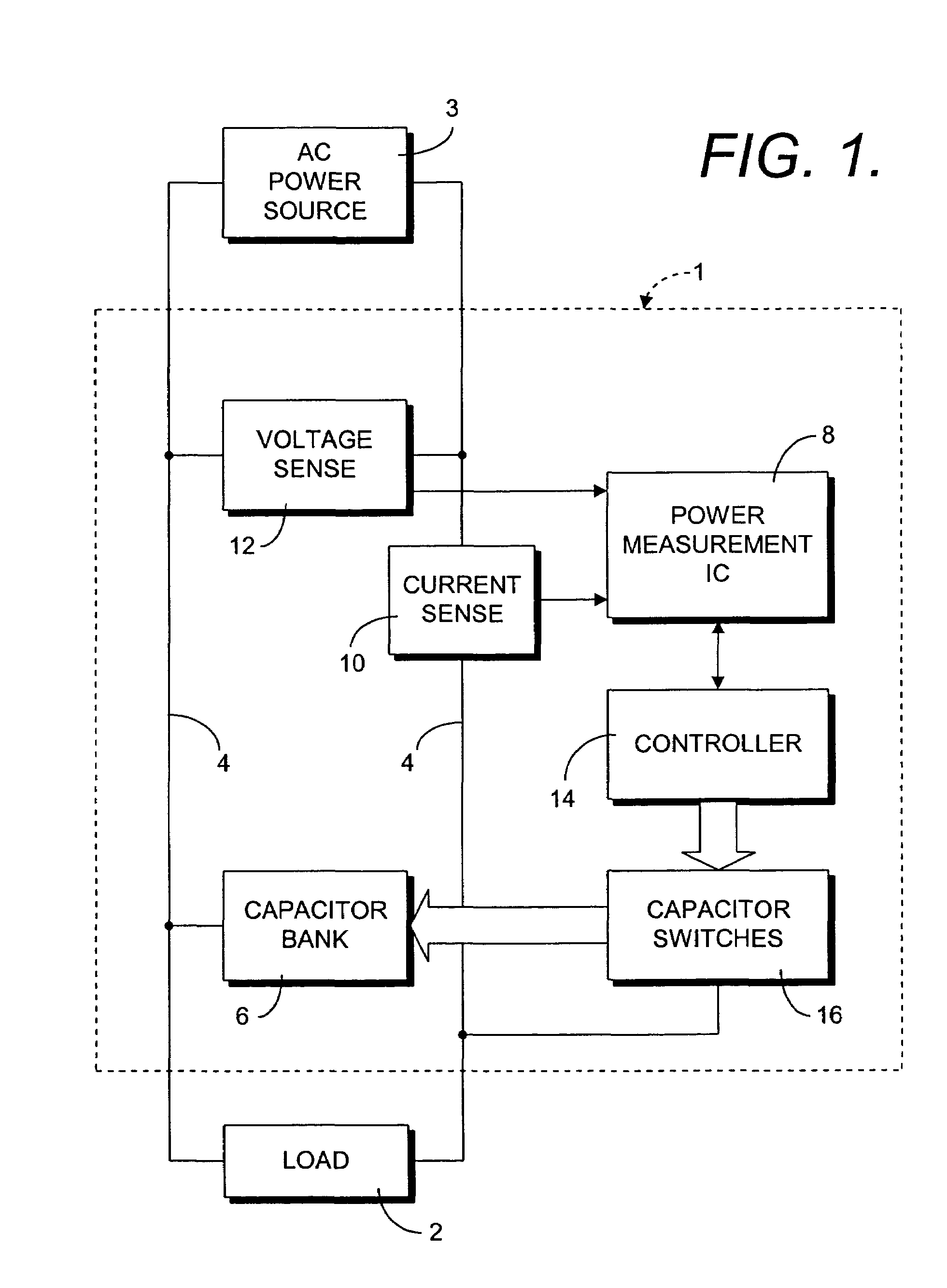
[0031]In a preferred or first embodiment of the apparatus 1, the chip 8 is a model ADE7753 manufactured by Analog Devices, Inc. Documentation for this chip is available on the website identified above. The ADE7753 periodically derives a signed reactive power value, among other parameters, from the voltage and current values measured through the current and voltage sensing circuitry 10 and 12 and stores this value in a particular register within the chip 8 which can be queried by the controller 14, over a serial interface between the chip 8 and the controller 14. From the signed reactive power value, the controller 8 can calculate the value of capacitance required to compensate for the reactive component of power drawn by the load 2, using known formulas. From the known voltage of the power line 4, or a measured voltage value stored in an appropriate register, and the measured reactive power, the reactive current drawn by the load 2 can be calculated, along with the reactive impedanc...

second embodiment

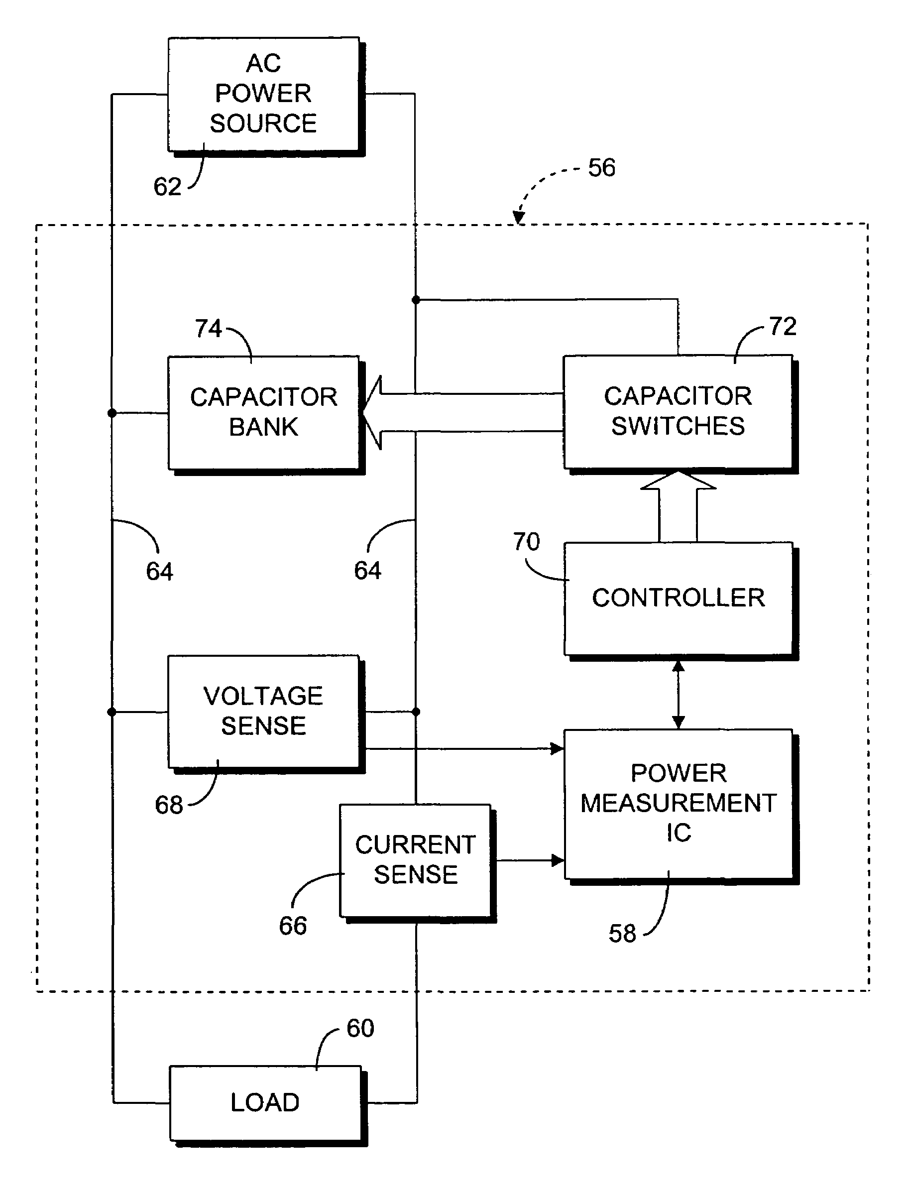
[0034]FIGS. 5 and 6 illustrate a power factor correction process 54 (FIG. 5) and apparatus 56 (FIG. 6) which form the present invention. The process 54 and apparatus 56 are particularly adapted for use with a power measurement integrated circuit 58 which does not provide a signed reactive power value but which does provide values of active power and apparent power, from which a power factor value for a load 60 may be obtained. Such a chip 58 could be implemented by a model CS5460 manufactured by Cirrus Logic, Inc. Documentation for the CS5460 can be obtained from the website listed above.

[0035]Referring to FIG. 6, the apparatus 56 provides power factor correction for the load 60 which receives electrical power from an AC power source 62 by way of a power line 64. The apparatus 56 includes current sensing circuitry 66 and voltage sensing circuitry 68 which may be similar to the circuitry 10 and 12 of the apparatus 1. The circuitry 66 and 68 are coupled to the chip 58 by means of resp...


PUM


Abstract

An automatic power factor correction system, for an electrical power installation drawing varying levels of reactive power, measures an electrical parameter of the power drawn by a load of a power installation using a power measurement integrated circuit, the parameter being capable of indicating a level of reactive power drawn by the load, and couples a combination of capacitors to the power line to compensate for the level of reactive power indicated by the electrical parameter measured. In a first embodiment of the invention, the combination of power factor compensating capacitors is calculated from a signed value of reactive power drawn by the load. In a second embodiment, the compensating capacitor combination is calculated from a value of power factor for the load which is calculated from a ratio of an active power value to an apparent power value.

Description

CROSS-REFERENCE TO RELATED APPLICATIONS[0001]This is a continuation-in-part of U.S. patent application, Ser. No. 10 / 162,406 for AUTOMATIC POWER FACTOR CORRECTION SYSTEM filed Jun. 4, 2002, now U.S. Pat. No. 6,700,358, which is a continuation-in-part of U.S. patent application, Ser. No. 09 / 874,690 for AUTOMATIC POWER FACTOR CORRECTION SYSTEM filed Jun. 5, 2001, now U.S. Pat. No. 6,462,519, both applications being incorporated herein by reference.BACKGROUND OF THE INVENTION[0002]The present invention relates to electrical power control circuitry and, more particularly, to an improved system for monitoring and correcting the power factor of a power installation which employs a power measurement integrated circuit.[0003]Electrical power is an enormously versatile and convenient source of energy. However, there are costs in generating and distributing electrical energy, which tend to increase when demand for electrical power increases. For this reason, there is always a motivation for in...

Claims


Application Information

Patent Timeline
Patent Type & Authority Patents(United States)
IPC IPC(8): G05F1/70H02J3/18
CPCG05F1/70H02J3/1871H02J3/1828Y02E40/30H02J2310/20
Inventor MCDANIEL, WILLIAM D.MCDANIEL, GAIL A.MCDANIEL, TIMOTHY J.
Owner MCDANIEL WILLIAM D
Why Eureka
Try Eureka