Unlock instant, AI-driven research and patent intelligence for your innovation.
Multilens optical assembly for a diagnostic device
What is Al technical title?
Al technical title is built by PatSnap Al team. It summarizes the technical point description of the patent document.
a diagnostic device and optical assembly technology, applied in the direction of optical radiation measurement, fluorescence/phosphorescence, laboratory glassware, etc., can solve the problems of not being expensive, fluorescence detection assay, and needing special fluorescence readers, so as to enhance the brightness of the center region
Inactive Publication Date: 2006-02-21
QN DIAGNOSTICS LLC
View PDF9 Cites 17 Cited by
Summary
Abstract
Description
Claims
Application Information
AI Technical Summary
This helps you quickly interpret patents by identifying the three key elements:
Problems solved by technology
Method used
Benefits of technology
Benefits of technology
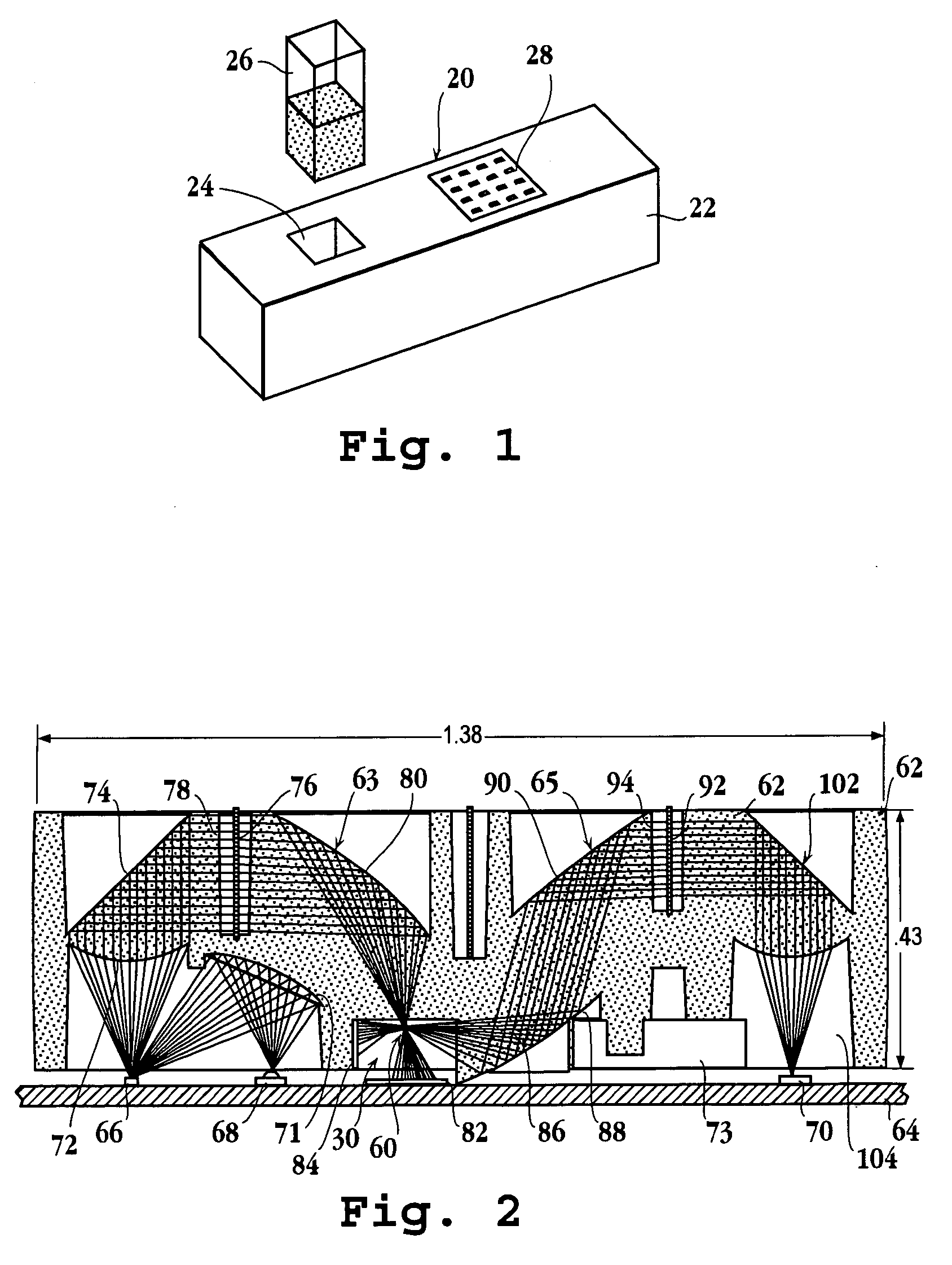
[0016]In all of these embodiments, the light source is preferably a light-emitting diode (LED), and preferably one that emits a desired fluorescence excitation wavelength, e.g., in the blue or green. The first optical surface encountered by the excitation light from the LED may have a curvature that acts to offset light rays from the diode toward the center of the optical field formed by the first optical surface, to enhance the brightness of the center region of the optical field.
Problems solved by technology
One limitation of fluorescence-detection assay, however, has been the need for special fluorescence readers.
Although such readers may not be expensive, they have prevented widespread adoption of fluorescence assays in home-testing and in small-clinic medical or veterinary settings, and in other medical or field diagnostic applications, e.g., in the testing of air or water for bioagents, that would benefit from small, easily portable and / or disposable assay equipment.
Method used
Image
Click on the blue label to locate the original text in one second.
Reading with bidirectional positioning of images and text.
Examples
Embodiment Construction
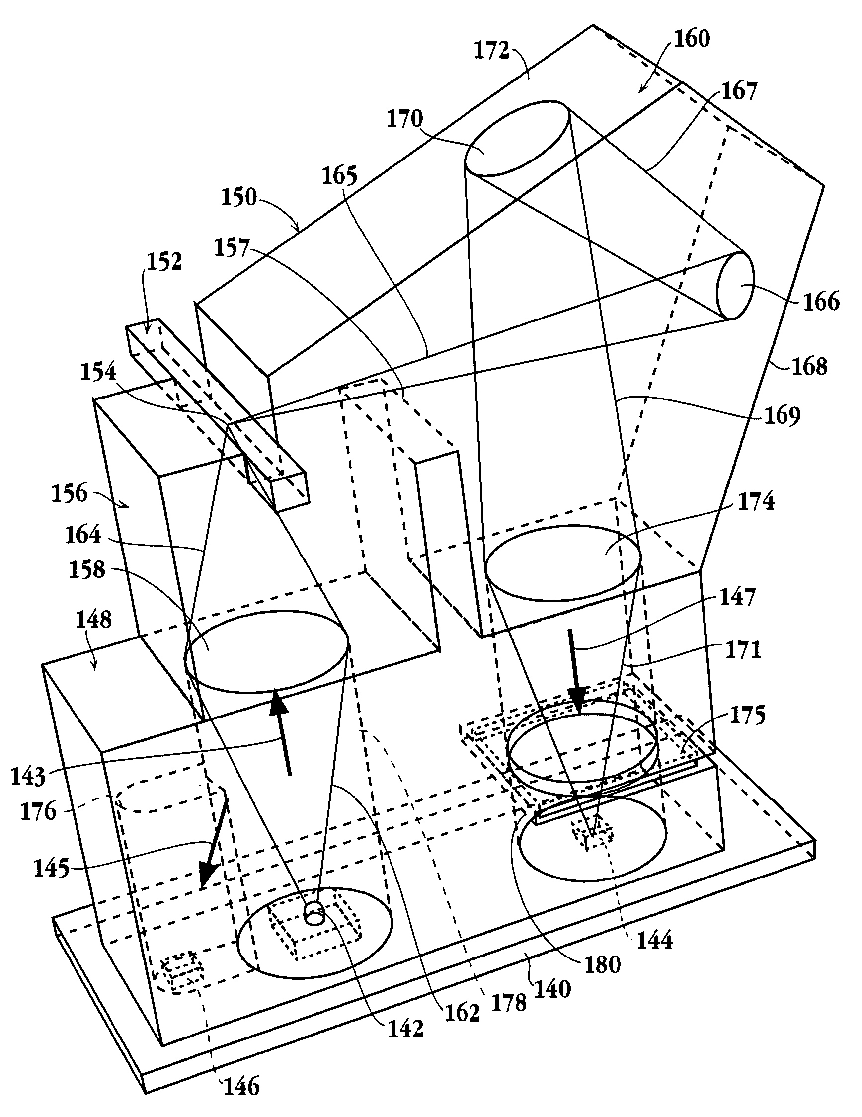
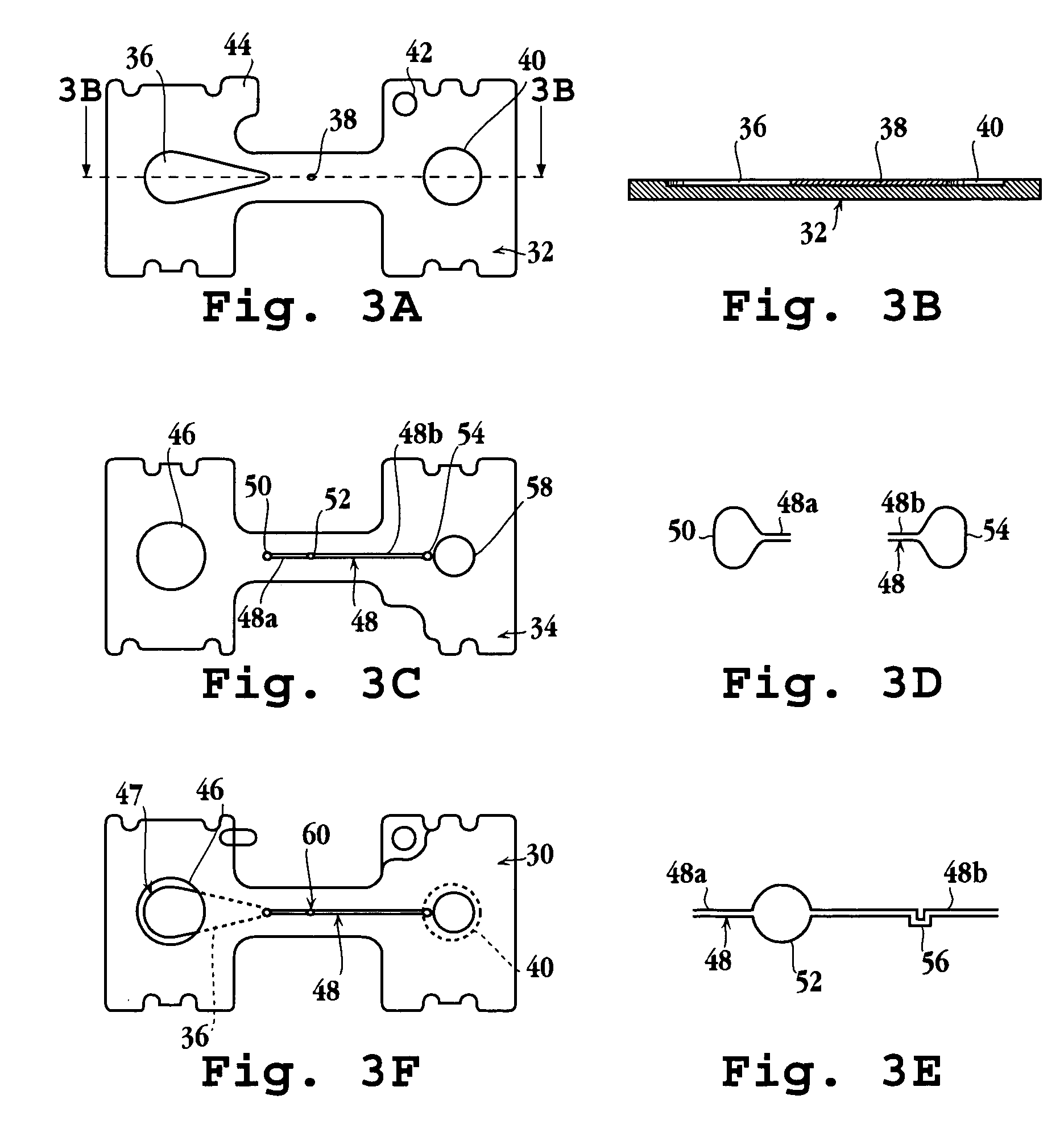
[0031]The present invention includes a multisurface optical module in a fluorescence-detection diagnostics device or apparatus. As will be described below, the optical module is preferably formed as a unitary (single-piece) molded article, e.g., molded plastic article, and can be tailored to a variety of assay devices and formats, such as a microfluidics format, a multiple-sample format, and an array format. It can be manufactured to small dimensions, e.g., for use in a microfluidics or other small device, and can be integrated with sample-handling elements, e.g., by laminating a microfluidics plate to one of the assembly surfaces. The module, including attached fluid-handling structure, may be a disposable cartridge that can be removably inserted into a reader apparatus, or may be a fixed element of a disposable device.
[0032]In its most general aspect, the optical module includes (i) an upstream portion having a first focusing optical surface for directing excitation light from a l...
PUM
Property
Measurement
Unit
volume
aaaaa
aaaaa
fluorescence emission wavelengths
aaaaa
aaaaa
volume
aaaaa
aaaaa
Abstract
A diagnostics apparatus for detecting fluorescence events related to the presence of an analyte in a sample is disclosed. The apparatus includes a housing, a source of excitation light and a photodetector, and a unitary multi-surface optical module. The optical module is integrally formed and composed of an upstream portion having a focusing optical surface for directing excitation light from the light source to a focal region within an analyte-detection zone in the apparatus, and a downstream portion having a second focusing powered optical surface and at least one reflecting surface for directing fluorescence-emission light produced by fluorescence events within the detection zone, in a direction substantially normal to the path of the excitation light onto the photodetector. The optical module is adaptable to a variety of assay formats, including multiple-sample, sample-array, and disposable-cartridge formats.
Description
[0001]This application is a continuation-in-part of U.S. patent application Ser. No. 10 / 705,162 filed on Nov. 6, 2003 now U.S. Pat. No. 6,929,945, which claims the benefit of U.S. provisional patent application No. 60 / 511,798 filed on Oct. 16, 2003, now abandoned, both of which are incorporated herein by reference in their entirety.FIELD OF THE INVENTION[0002]The present invention relates to a multilens optical assembly for use in a fluorescence-detection diagnostic device, such as a microfluidics diagnostic device, immunosorbent assay or gene chip, and preferably, to such an assembly formed as a unitary, i.e., single-piece polymer structure, e.g., by injection molding.BACKGROUND OF THE INVENTION[0003]There are many types of diagnostics devices that use optical sensing, such as fluorescence or absorption, to detect the presence or amount of analyte in a sample, e.g., blood, urine, or saliva sample. Fluorescence detection, in particular, has been adapted to many different types of en...
Claims
Application Information
Patent Timeline
Application Date:The date an application was filed.
Publication Date:The date a patent or application was officially published.
First Publication Date:The earliest publication date of a patent with the same application number.
Issue Date:Publication date of the patent grant document.
PCT Entry Date:The Entry date of PCT National Phase.
Estimated Expiry Date:The statutory expiry date of a patent right according to the Patent Law, and it is the longest term of protection that the patent right can achieve without the termination of the patent right due to other reasons(Term extension factor has been taken into account ).
Invalid Date:Actual expiry date is based on effective date or publication date of legal transaction data of invalid patent.

