
Network appliance combining asynchronous notification with interactive network transfer protocol server

a network appliance and asynchronous notification technology, applied in the field of computer networks, can solve the problems of affecting productivity, affecting network performance, and affecting maintenance, so as to minimize the effort of the user in accessing information about the triggering event, minimize the burden on the network, and minimize the effect of network traffic directed to the network managemen

Inactive Publication Date: 2006-02-21
HEWLETT-PACKARD ENTERPRISE DEV LP
View PDF3 Cites 4 Cited by
  • Summary
  • Abstract
  • Description
  • Claims
  • Application Information

AI Technical Summary

Benefits of technology

[0017]One advantage of the present invention is that it provides a familiar interface for a network administrator to manage a network. For example, the World Wide Web is not only a standard interface for the Internet, but also for intranets. Also, there is a trend to provide network appliances with web interfaces. Thus, minimal training is required for a network administrator to learn the interface.
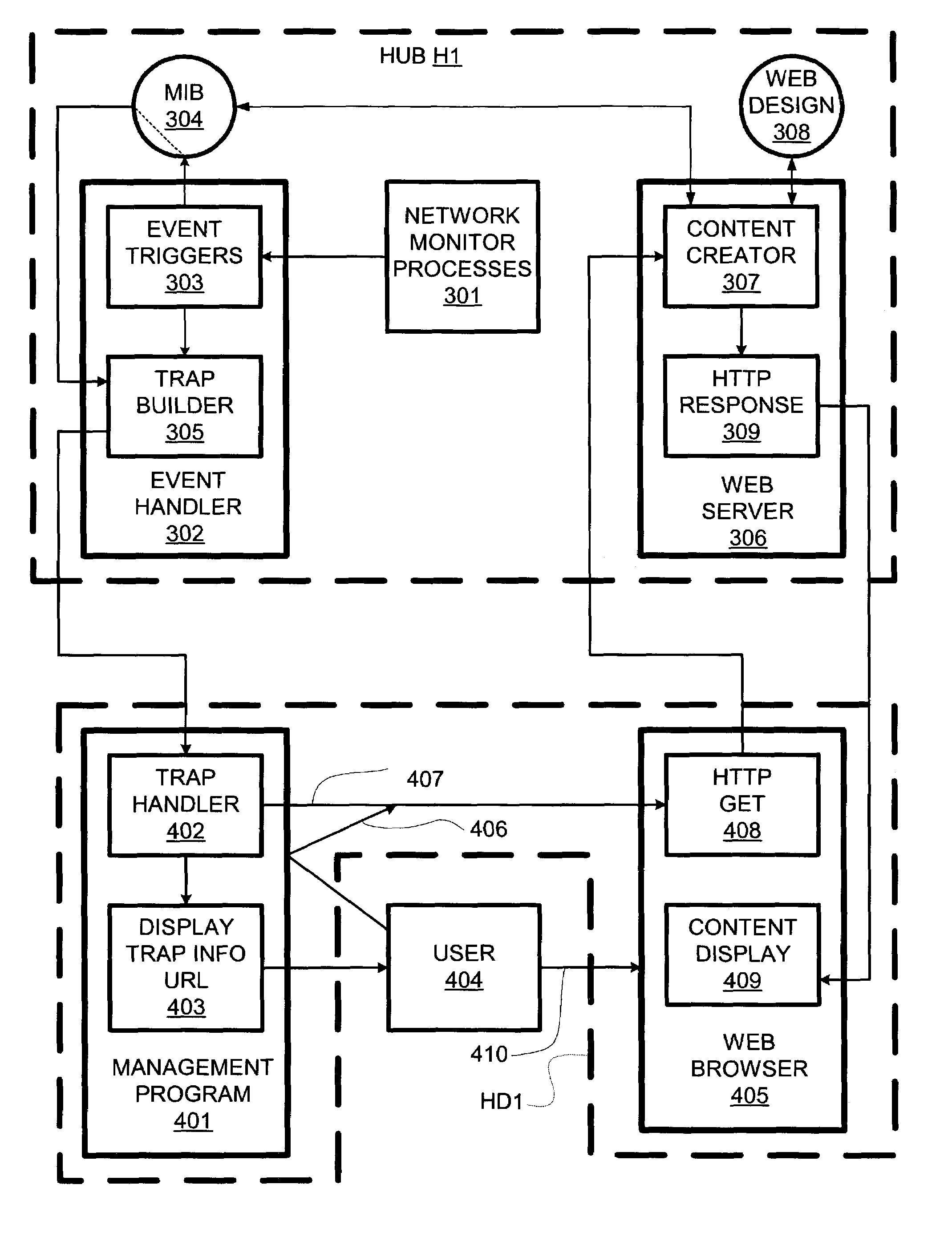
[0018]A second advantage of the invention, which is both subtle and surprising, is that it obviates the need to update the network management software as new types of network appliances are incorporated into the network. All the information regarding a triggering event and the options for handling it are handled by the web server on the network appliance. The network management program on the network management station does not need to have a characterization of each network appliance. The only requirement is that the network management program be able to communicate the URL associated with the triggering event to the user or to the user's browser.
[0019]A third advantage is that effort on the user's part in accessing information about the triggering event is minimized. In a typical realization of the invention, one point-and-click operation is required to access the relevant page of the appliance server; one more point-and-click is often sufficient as a response to the triggering event.
[0020]A fourth advantage is that network burden is minimized. Since the network appliance provides the notification asychronously, there is no need for a network management station to maintain a continuous connection with or to repeatedly poll appliances employing the present invention. Thus, network traffic directed to network management is minimized when there are no problems requiring notification. These and other features and advantages of the invention are apparent from the description below with reference to the following drawings.

Problems solved by technology

To a lesser degree, productivity is adversely affected when network performance is impaired.
Unfortunately, such maintenance can also be quite difficult.
In many cases, the information included in the notification is not comprehensive.
Transmitting all pertinent information regarding triggering events might unduly burden a network; also, the pertinence of the information might wane if the administrator does not address the notification immediately.
While such a solution appears feasible in a network in which all appliances (including the network management station) are from a single vendor, it is less workable where there are appliances from multiple vendors involved.
Thus, however they are allocated between the administrator and the network management station, the tasks of notification data interpretation and of determining responses can be unduly burdensome.

Method used


Image

  • Network appliance combining asynchronous notification with interactive network transfer protocol server
  • Network appliance combining asynchronous notification with interactive network transfer protocol server
  • Network appliance combining asynchronous notification with interactive network transfer protocol server

Examples


Embodiment Construction

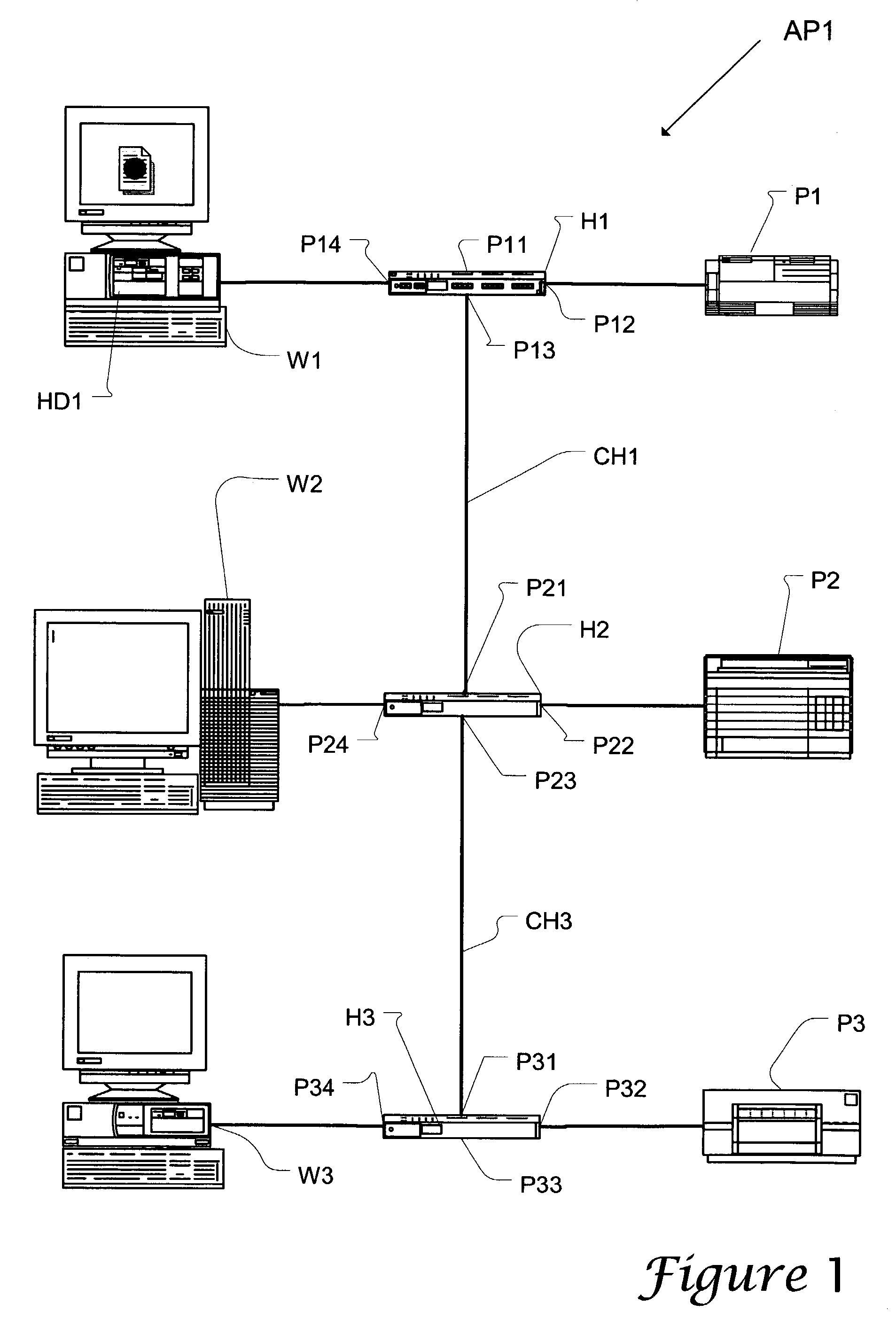
[0024]In accordance with the present invention, a network system AP1 includes three repeater hubs H1, H2, and H3, three computer workstations W1, W2, and W3, a monochrome laser printer P1, a color laser printer P2, and a color ink-jet printer P3, and eight cables. Six of the eight cables are coupled to the six node appliances W1, W2, W3, P1, P2, P3; the other two cables CH1 and CH3 couple hubs.

[0025]Hub H1 has four ports, P11, P12, P13, and P14. Port P11 is not being used. Port P12 is coupled to printer P1. Port P13 is coupled to hub H2 via cable CH1. Port P14 is coupled to workstation W1. Workstation W1 includes a hard disk HD1 on which a network management program and a web browser are stored.

[0026]Hub H2 also has four ports, P21, P22, P23, and P24. Port P21 is coupled to port P13 of Hub H1 via cable CH1. Port P22 is coupled to printer P2. Port P23 is coupled to hub H3 via cable CH3. Port P24 is coupled to workstation W2.

[0027]Hub H3 has four ports, P31, P32, P33, and P34. Port P3...


PUM


Abstract

A network hub responds to network problems by generating traps in conformance with the Simple Network Management Protocol (SNMP). In generating a trap, the hub includes a Uniform Resource Locator (URL) as a text string incorporated in the trap. The network hub incorporates a server conforming to the HyperText Transfer Protocol (HTTP) used by the World Wide Web. The server has its own home page and the URL incorporated in the trap points to a subpage of that home page. When a network management station receives the trap, the URL is displayed as a hypertext link. When the link is “clicked”, a web browser is activated and is pointed to the URL so that an HTTP “get” command is transmitted. When the hub receives the “get” command, it responds by generating the requested subpage. The subpage is presented as a World Wide Web page with a full presentation of data relating to the event triggering the trap. In addition, the subpage includes active elements (hypertext links, buttons, and / or menu items) that when activated initiate a course of action to address the detection of the network problem.

Description

CROSS REFERENCE TO RELATED APPLICATION(S)[0001]This is a divisional of application Ser. No. 09 / 217,684 filed on Dec. 21, 1998 now U.S. Pat. No. 6,621,823, which is hereby incorporated by reference herein.BACKGROUND OF THE INVENTION[0002]The present invention relates to computer networks and, more particularly, to a network appliance that monitor parameters (e.g., related to their own and / or a network's performance). A major objective of the present invention is to facilitate fault handling in a computer network.[0003]Computer networks allow computer users to communicate, collaborate, and share resources. While there are peer-to-peer computer networks, most sophisticated networks use network infrastructure appliances, e.g., hubs, switches and routers, to manage communication between end-node appliances, e.g., computers, printers, modems, instrumentation, etc. A typical network infrastructure appliance includes multiple ports, each of which can be coupled to an end-node appliance or a...

Claims


Application Information

Patent Timeline
Patent Type & Authority Patents(United States)
IPC IPC(8): G01R31/08G06F13/00H04L69/40
CPCH04L41/0213H04L41/06H04L43/0847H04L41/22H04L43/06
Inventor MELLQUIST, PETER E.VANZANTE, CRAIG A.BAUMGARTNER, JIM A.
Owner HEWLETT-PACKARD ENTERPRISE DEV LP
Learn More