FDM-CDMA transmitting method, FDM-CDMA receiving method, FDM-CDMA transmitting device and FDM-CDMA receiving device

a technology of cdma and transmitting method, applied in the field of radio broadcasting and radio communication technologies, can solve the problems of detecting an error in the receiving timing clock, affecting the call quality, and affecting the reception quality,

Inactive Publication Date: 2006-02-21
NEC CORP
View PDF15 Cites 6 Cited by
  • Summary
  • Abstract
  • Description
  • Claims
  • Application Information

AI Technical Summary

Benefits of technology

[0021]The FDM-CDMA receiving method may further include the steps of generating N vectors, as inverse spreading codes, which are +1 or −1 polarity and are unique to users at a transmission side and multiplying the nth (n is an integer of 1 to N) digital data before the demodulation and nth vector corresponding thereto In this case, the inverse spread modulation may be performed thereby on the N pieces of digital data after the demodulation. Thus, the inverse spread modulation can be performed easily in a time-fixed manner.

Problems solved by technology

In long distance radio broadcasting and mobile communication, call quality is extremely unstable due to the multiple propagation in propagation paths.
However, the recent data communication typified by the radio and the Internet suffers from extremely serious problems due to the multiple propagation.
As a result of the relative detection, an error in the receiving timing clock is detected.
However, since the current communication and broadcasting systems adopt completely different communication methods, the integration of communication and broadcasting is extremely difficult.
Furthermore, since the CDMA receiving device must perform relative detection of many chips in an extremely fast manner in the conventional CDMA method, the synchronization of PN codes requires a significant amount of time for inverse spread modulation at the time of the receipt in particular.
In a system the cell switching is performed frequently such as in a mobile communication, the long time required for synchronization could be a big problem.

Method used


Image

  • FDM-CDMA transmitting method, FDM-CDMA receiving method, FDM-CDMA transmitting device and FDM-CDMA receiving device
  • FDM-CDMA transmitting method, FDM-CDMA receiving method, FDM-CDMA transmitting device and FDM-CDMA receiving device
  • FDM-CDMA transmitting method, FDM-CDMA receiving method, FDM-CDMA transmitting device and FDM-CDMA receiving device

Examples


Embodiment Construction

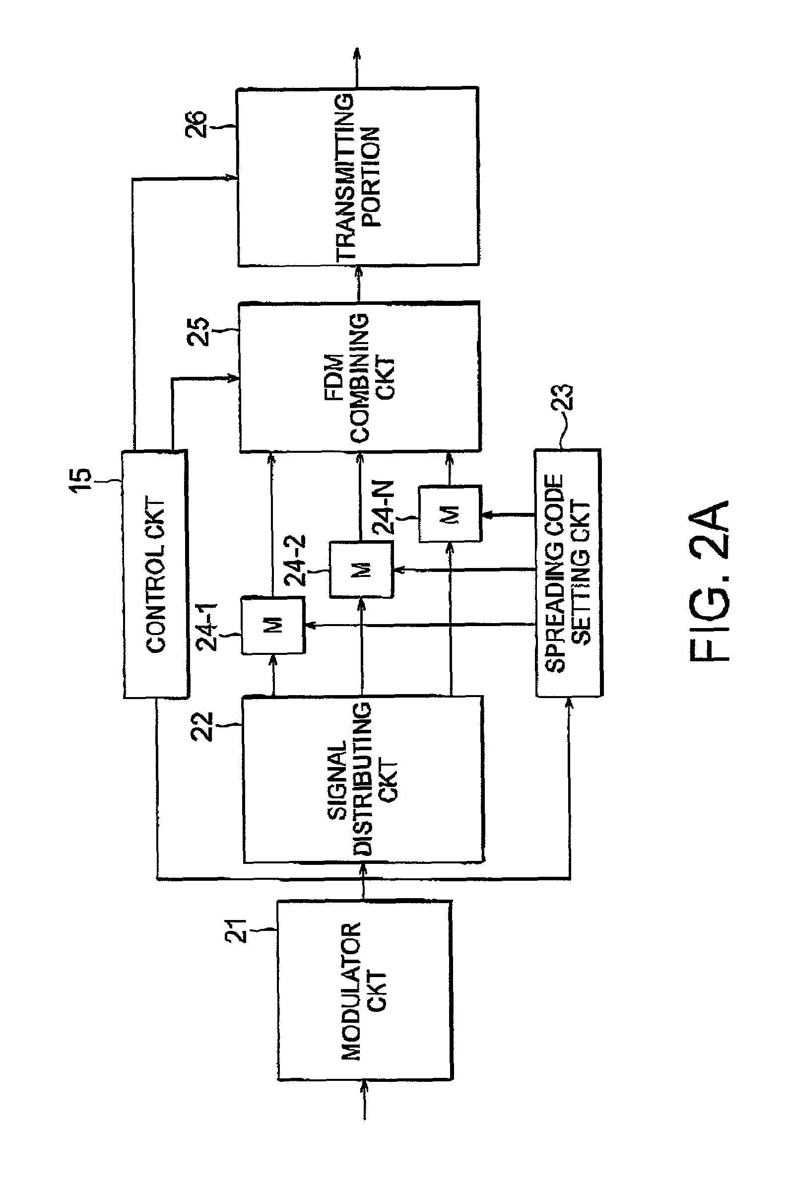
[0037]Embodiments of the present invention will be described below in detail with reference to the drawings. FIGS. 2A and 2B are a block diagram showing a configuration of an FDM-CDMA communication device, which is an embodiment of the present invention. FIG. 2A is a block diagram of an FDM-CDMA transmission device, and FIG. 2B is a block diagram of an FDM-CDMA receiving device.

[0038]The FDM-CDMA transmission device shown in FIG. 2A comprises a modulator circuit 21 for performing primary modulation on digital data to be transmitted, a signal distributing circuit 22 for distributing the digital data to the number of frequency channels equal to the number N in the FDM method in order to assign the digital data to each frequency channel, a spreading code setting circuit 23 for generating spreading codes in the CDMA method, multipliers 24-1 to 24-N for multiplying the digital data output from the signal distributing circuit 22 by a spreading code in order to perform spread modulation on...


PUM


Abstract

A spreading code setting circuit generates N vectors, as spreading codes, which are +1 or −1 polarity and are unique to users. A multiplier multiplies the nth data and the nth spreading code corresponding thereto for the spread modulation. An FDM combining circuit modulates N pieces of data according to the FDM method. A FDM separating circuit demodulates received signals according to the FDM method. An inverse spreading code setting circuit generates N vectors, as inverse spreading codes, which are +1 or −1 polarity and are unique to users at the transmission side. A multiplier multiplies the nth data and the nth inverse spreading code corresponding thereto for inverse spread modulation.

Description

BACKGROUND OF THE INVENTION[0001]The present invention relates to the radio broadcasting and the radio communication technologies, more particularly to an FDM-CDMA transmission method, an FDM-CDMA receiving method, an FDM-CDMA transmitting device, and an FDM-CDMA receiving device, which can integrate the FDM-method broadcasting and the CDMA-method communication.[0002]In long distance radio broadcasting and mobile communication, call quality is extremely unstable due to the multiple propagation in propagation paths. Recently, in mainstream radio and / or wireless telephones are the main stream, sufficient quality has been obtained by frequency modulation (FM) and / or the amplitude modulation (AM). However, the recent data communication typified by the radio and the Internet suffers from extremely serious problems due to the multiple propagation.[0003]Today, two modulation methods are adopted mainly in order to address fading due to the multiple propagation. One modulation method is a co...

Claims


Application Information

Patent Timeline
Patent Type & Authority Patents(United States)
IPC IPC(8): H04B7/216H04B1/69H04B1/707H04J3/06H04J1/00H04J11/00H04J13/00H04L5/02H04L27/26
CPCH04L5/026
Inventor ICHIYOSHI, OSAMU
Owner NEC CORP
Why Eureka
Try Eureka