
Integrated switching and facility networks

a facility network and integrated switching technology, applied in the field of telecommunications, can solve the problems of high network operation cost, limited bandwidth sharing, and significant inefficiencies, and achieve the effect of simplifying network operations

Inactive Publication Date: 2006-02-21
AMERICAN TELEPHONE & TELEGRAPH CO
View PDF5 Cites 32 Cited by
  • Summary
  • Abstract
  • Description
  • Claims
  • Application Information

AI Technical Summary

Benefits of technology

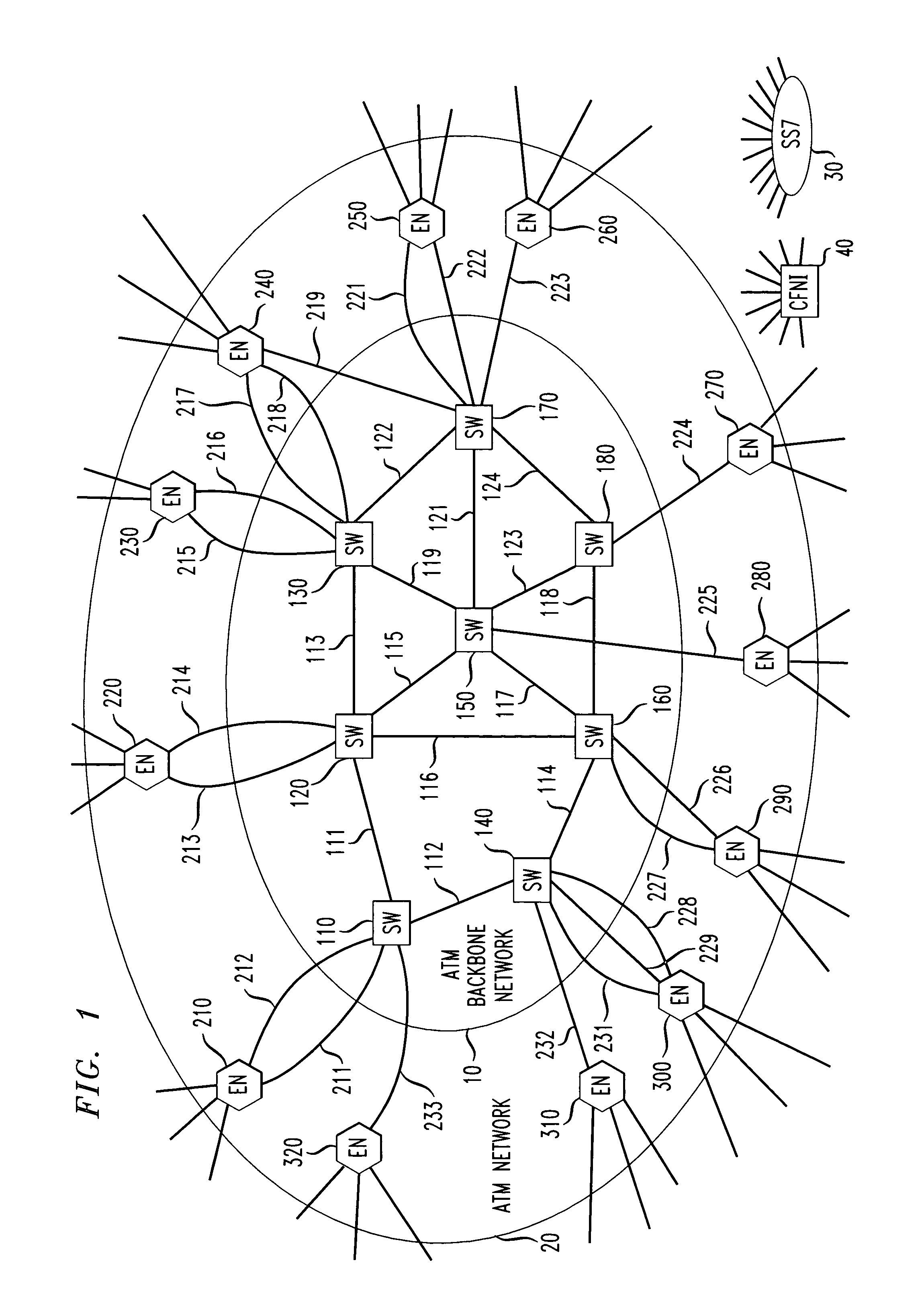
[0008]The problems associated with prior solutions for implementing ATM or IP / MPLS in a large-scale network are overcome by providing an efficient means by which capacity in the network is more fully shared without adversely affecting call or session setup latency, and at the same time simplifying network operations. This is achieved by performing the functions of route setup, route allocation, and capacity management in a network at the edges of the network. By “edges” what is meant is the interface between an ATM switch or a IP / MPLS router of the network and another that is other than another ATM switch or IP / MPLS router of the network; for example, the interface between each ATM switch or IP / MPLS router and customers. In accordance with the principles disclosed herein, the edges contain nodes that form the interface between the ATM switches and IP / MPLS routers and the link(s) that interconnect them and the outside world. These nodes comprise controllers and other apparatus that in some cases may be incorporated in, or connected as adjuncts to, the ATM switches or IP / MPLS routers.
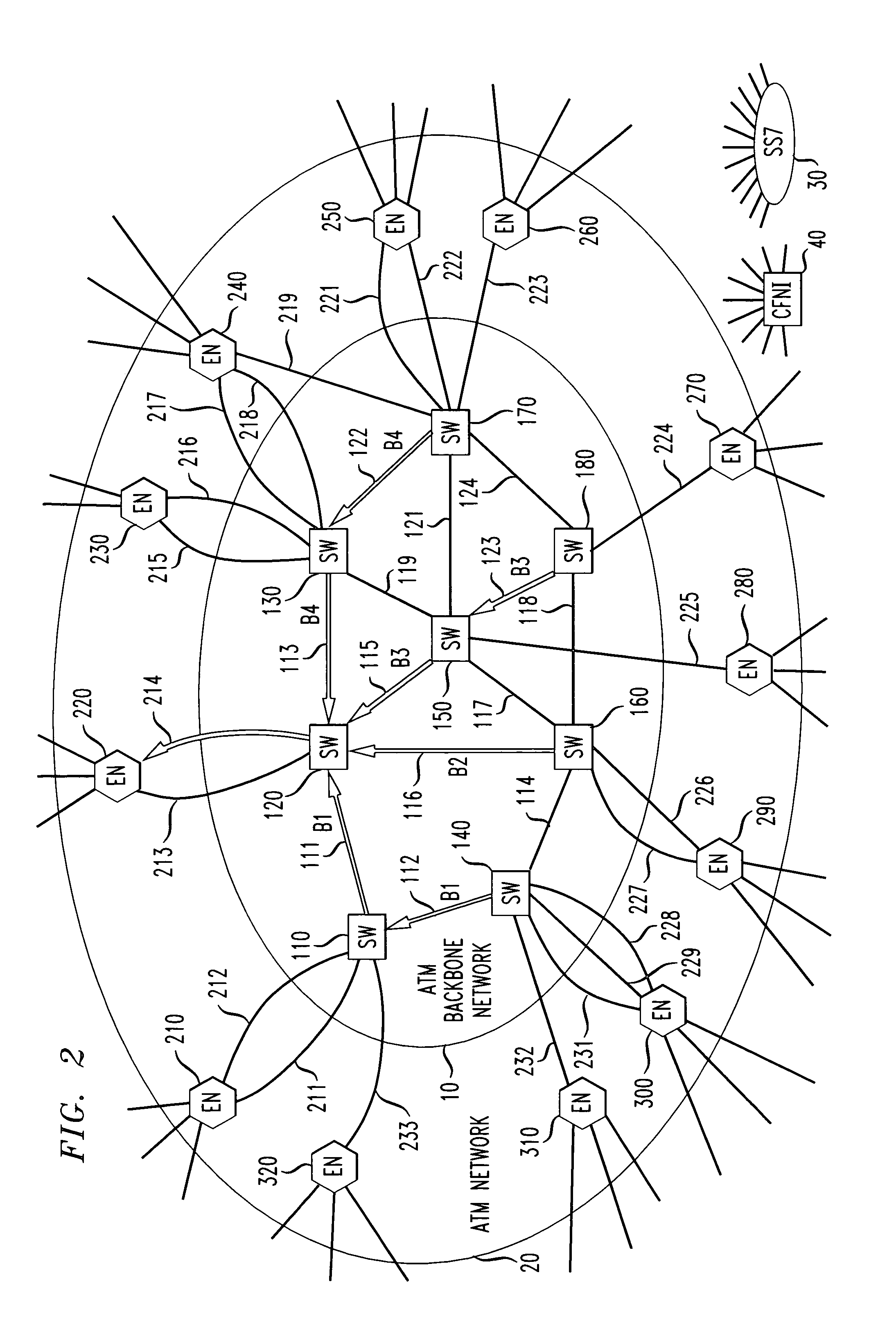
[0009]In an ATM network, edge nodes assign calls to virtual paths based on the destination of the call and the current load status of each of a number of preselected paths. Thus, each call is assigned a VPI (Virtual Path Identifier) corresponding to the path chosen and a VCI (Virtual Circuit Identifier) corresponding to the identity of the call at that edge node. The ATM backbone nodes route calls based solely on the VPI. Destination based routing allows VPIs to be shared among routes from different sources to the same destination.
[0010]Capacity management and load balancing is achieved through a Fabric Network Interface (FNI) that is present in each of the edge nodes along with a Centralized FNI (CFNI), that maintains backbone link status. In an ATM network, the FNI is responsible for keeping track of the load on each access link from its edge node to the backbone ATM switch it homes onto, as well as the load on each, backbone link of the calls it originated. This load is measured in normal bandwidth requirements for CBR services and could be measured in effective bandwidths for other services. The FNI is also responsible for periodically sending its information to the CFNI. The CFNI collects the received information and calculates the bandwidth used on each backbone link. It then computes a link status for each access and backbone link and sends this status information to each FNI. This information assists the FNIs in carrying out their tasks.
[0013]Similarly, in an IP / MPLS network, edge nodes assign calls or sessions or IP flows to label switched paths based on the destination of the session and the current load status of each of a number of pre-selected paths. Thus, each session is assigned a stack of labels corresponding to the path chosen and a label identifier corresponding to the identity of the session at that edge node. That is, the label identifier identifies the session in a predetermined direction. The IP / MPLS router nodes route IP packets belonging to sessions based solely on the stack of labels and label identifiers. Destination based routing allows the stacks of labels to be shared among routes from different sources to the same destination.

Problems solved by technology

The partitioning of a circuit-switched network into logical and physical layers results in significant inefficiencies.
Physical diversity is difficult to plan for such networks due to the indirect mapping between the logical and physical layers, and such networks have high operations costs due to the constant need to resize trunk groups between switch pairs as the load changes or shifts.
Also, sharing of bandwidth is limited to the possible alternate paths at the logical layer.
Finally, such networks are difficult to scale as network traffic increases because each switch that is added to the network must be interconnected to all other switches at the logical layer, trunks on existing switches must be re-homed to the new switch, and the routing tables at all other switches in the network must be updated.
All of this creates substantial operational load on the network provider.
Since facilities are in units of T3 capacity, fragmentation of trunk groups also increases with the size of the network.
However, the standard procedures of an ATM network require the ATM switches in the network to perform a substantial amount of computation, which is burdensome and which makes it difficult to operate the network at high load volumes.

Method used


Image

  • Integrated switching and facility networks
  • Integrated switching and facility networks
  • Integrated switching and facility networks

Examples


example

A Call Flow Using the RSD

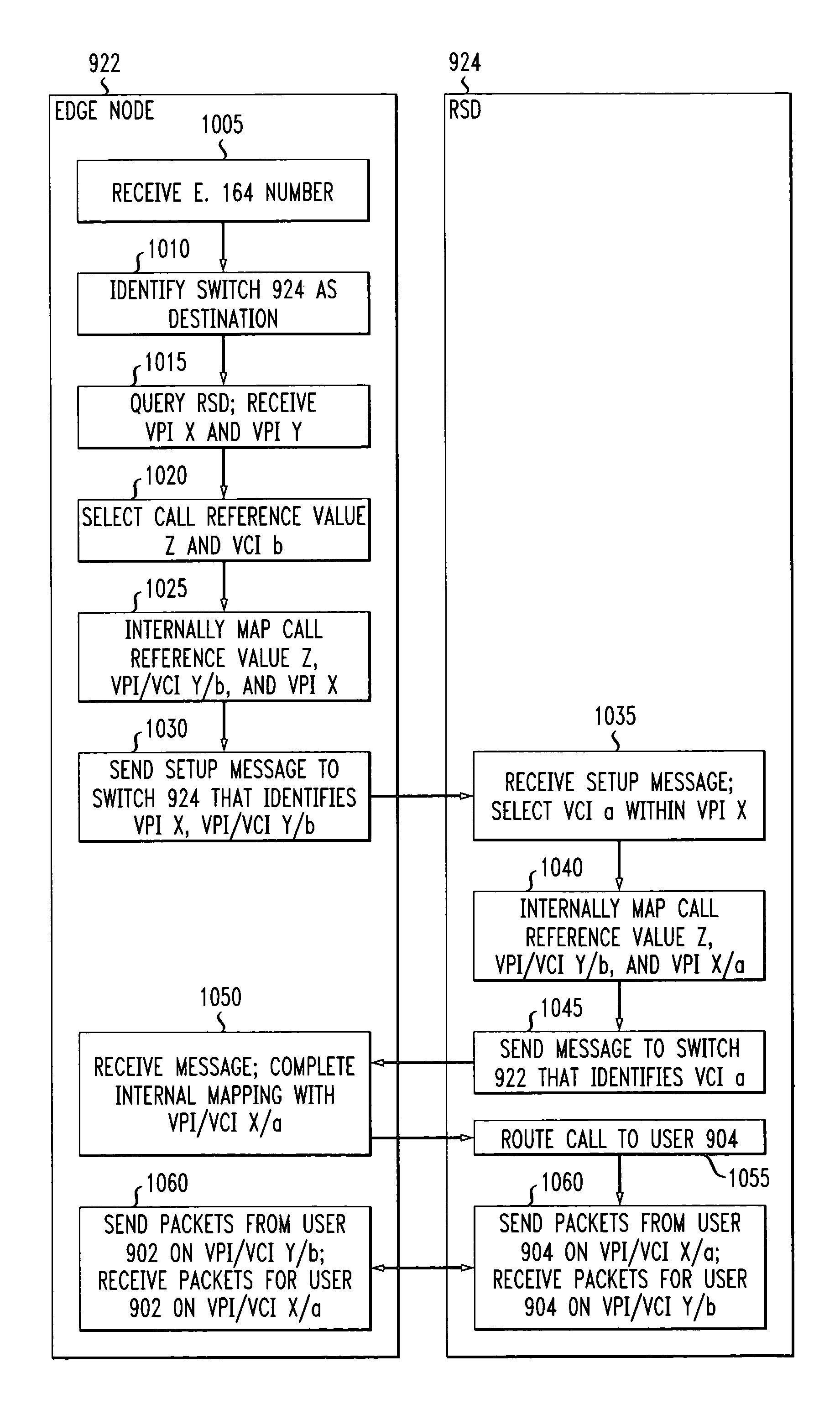
[0137]FIG. 8 shows a call flow between an edge node 802 and an RSD 804 showing how the edge node obtains a VCI for the call from the RSD. For example, edge node 802 is analogous to an edge node 620 of FIG. 6, and RSD 804 is analogous to CRSDS 630 of FIG. 6. The message protocol used for RSD queries might be SS7, or it could be any other data network protocol.

[0138]In a first step 810, edge node 802 receives a new call / communication for a session.

[0139]In a second step 820, edge node 802 sends source and destination information to RSD 804. Depending on the features supported by RSD 804, edge node 802 may send additional information, such as the priority of the session or the bandwidth required by the call / communication.

[0140]In a third step 830, RSD 804 receives the origin and destination information from edge node 802, and any other information sent as well.

[0141]In a fourth step 840, RSD 804 selects a route for the session, based on the source and destinati...


PUM


Abstract

The problems associated with prior solutions for implementing ATM or IP / MPLS in a large-scale network are overcome by providing an efficient means by which capacity in the network is more fully shared without adversely affecting call or session setup latency, and at the same time simplifying network operations. This is achieved by performing the functions of route setup, route allocation, and capacity management in a network at the edges (e.g., the interfaces existing between each ATM switch or IP / MPLS router and customers) of the network. In accordance with the principles disclosed herein, the edges contain nodes that form the interface between the ATM switches and IP / MPLS routers and the link(s) that interconnect them and the outside world. These nodes comprise controllers and other apparatus that in some cases may be incorporated in, or connected as adjuncts to, the ATM switches or IP / MPLS routers.

Description

RELATED APPLICATIONS[0001]This application is a continuation-in-part of U.S. patent application Ser. No. 09 / 219,319, filed on Dec. 23, 1998, now U.S. Pat. No. 6,463,062, which in turn is a continuation-in-part of U.S. patent application Ser. No. 08 / 974,172, filed on Nov. 19, 1997, now U.S. Pat. No. 6,081,506, all of which are incorporated by reference.BACKGROUND OF THE INVENTION[0002]ATM (Asynchronous Transfer Mode) is an exemplary telecommunications methodology using datagrams. As the volume of voice and voice-band calls is increasing markedly, and network providers are being challenged to offer these “plain old telephone” services at competitive prices, ATM presents an opportunity to reduce costs, and is therefore being considered for carrying circuit-switched voice traffic.[0003]Conventionally, a circuit switched network is managed by formulating a logical view of the network that includes a link between most pairs of network switches, and the network is managed at the logical le...

Claims


Application Information

Patent Timeline
Patent Type & Authority Patents(United States)
IPC IPC(8): H04L12/56H04Q11/04
CPCH04L12/5601H04L12/5602H04L45/10H04L45/50H04L45/505H04Q11/0478H04L2012/562H04L2012/5632H04L2012/5667H04L2012/5669H04L2012/5679H04L2012/568H04L2012/5629
Inventor BUYUKKOC, CAGATAYHOUCK, DAVID JJOHRI, PRAVIN KUMARMEIER-HELLSTERN, KATHLEEN S.MICHELSON, STEVEN M.MILITO, RODOLFO ALBERTO
Owner AMERICAN TELEPHONE & TELEGRAPH CO
Learn More