Link aggregation

a technology of link aggregation and network topology, applied in the field of communication systems, can solve the problems of affecting the performance and maintenance of the network, affecting the uptime and performance of the network, and affecting the reliability of the network, so as to reduce the size of the topology database, increase uptime and performance, and facilitate monitoring and observation of the status of the network link

Active Publication Date: 2008-08-19
CIENA
View PDF25 Cites 37 Cited by
  • Summary
  • Abstract
  • Description
  • Claims
  • Application Information

AI Technical Summary

Benefits of technology

[0013]To aggregate parallel links, a first node interacts with a second node across the parallel links connecting the two nodes. Once both nodes establish a common aggregation scheme, both nodes then may aggregate the common parallel links into a single aggregated link. Moreover, the first node can transmit data to the second node using the parallel link best optimized to transmit the data based on its status information, thereby increasing uptime and performance. Parallel links can be automatically selected for aggregation based on predetermined criteria, such as class of service.
[0014]The techniques of the present invention reduce the size of the topology database that is created at each node in the network as well as the amount of topology information that must be exchanged between nodes. Because an aggregated link is represented as a single link, the network topology does not need to change whenever a parallel link fails or is added to the network. This technique reduces the need and frequency at which new topology information floods the network. Additionally, a large number of nodes can be added to a network without surpassing the performance limits of the network. Network administrators can easily monitor and observe the status of network links and routes can be quickly generated because network operations are greatly simplified when fewer links are represented in the network topology.

Problems solved by technology

In large networks, the maintenance of network topology information can be difficult and cumbersome and can severely curtail the performance and maintenance of a network.
As network administrators deal with much larger and complex networks, many problems can arise as the number of nodes, parallel links and capacity per link increase.
Obviously, a network with hundreds or thousands of parallel links 140 could easily and frequently be flooded with new topology information generated from the change in status of the many connections between its many nodes, requiring very significant processing and communications bandwidth.
Maintaining topology information over such a network thus places a tremendous burden on network performance and scalability.
Also, many element management or network management systems using graphics to represent network topology cannot feasibly represent a network with many hundreds or even thousands of links.

Method used


Image

  • Link aggregation
  • Link aggregation
  • Link aggregation

Examples


Embodiment Construction

[0023]Embodiments of a method and system for link aggregation in networks are described. In the following description, for the purposes of explanation, numerous specific details are set forth in order to provide a thorough understanding of the embodiments of the present invention. It will be apparent, however, that embodiments of the present invention may be practiced without these specific details. In other instances, well-known structures and devices are shown in block diagram form in order to avoid unnecessarily obscuring the embodiments of the present invention.

Operational Overview

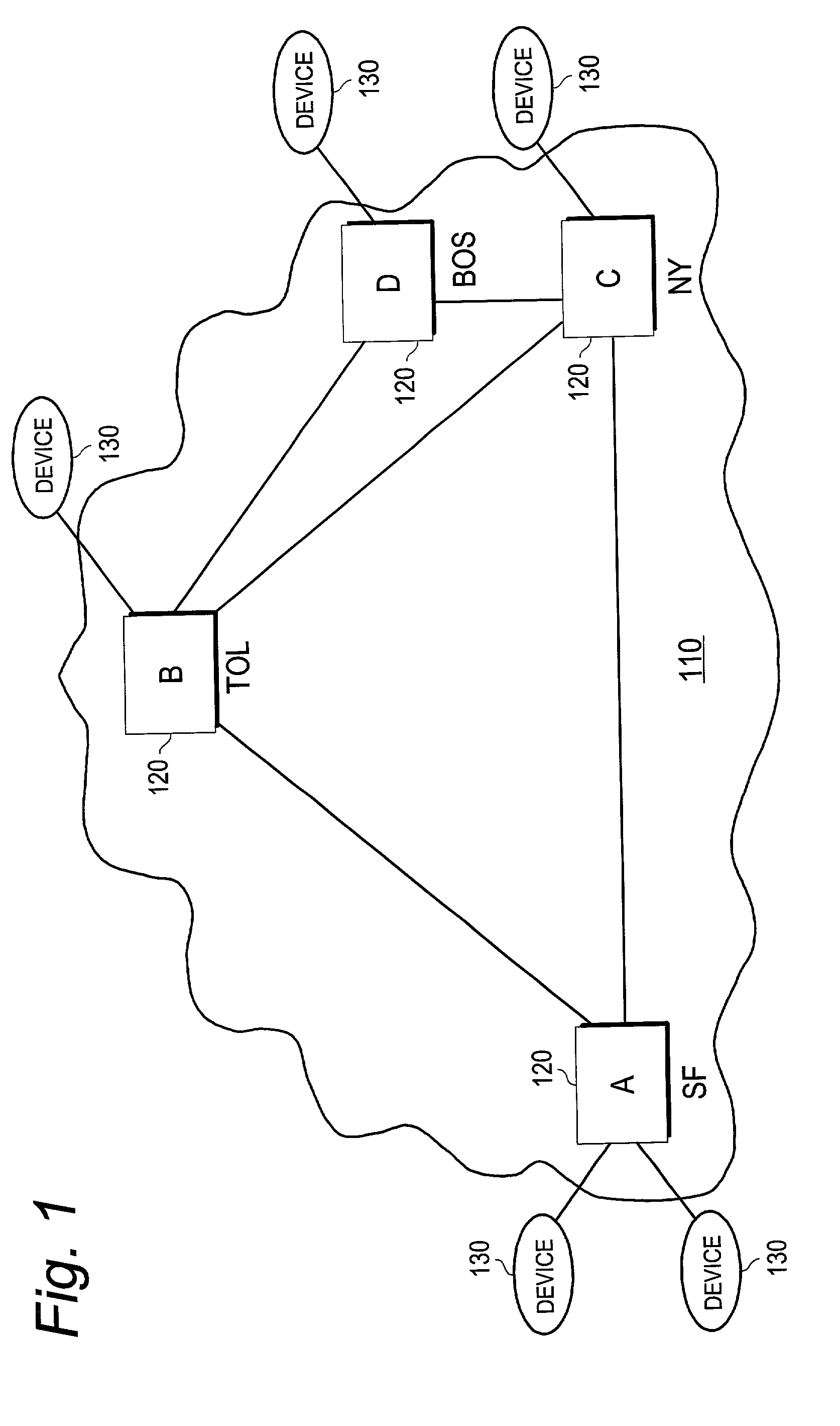
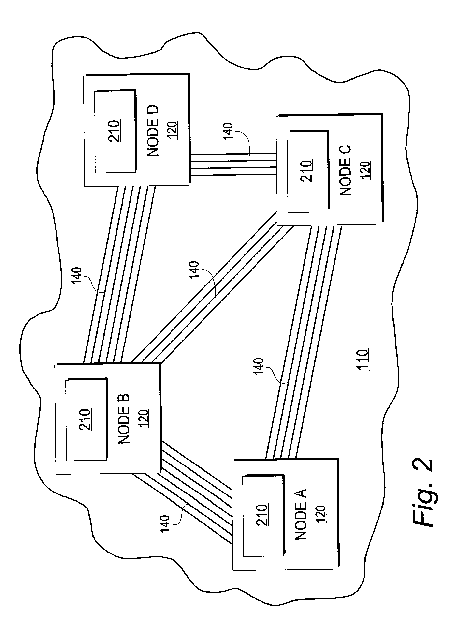
[0024]As discussed above, FIG. 1 is a schematic representing an exemplary network 110 configuration. The network 110 includes multiple nodes 120. FIG. 2 depicts the physical topology of the exemplary network 110 of FIG. 1, where nodes A, B, C and D are connected together by multiple parallel links 140.

[0025]In one embodiment of the invention, each node in a network configuration similar to network 110 ...


PUM


Abstract

A method and system for aggregating a plurality of parallel communications links transmitting data between adjacent nodes in a network is provided. The method simplifies network topology by replacing multiple parallel communications links between nodes in the network with a single aggregated link. The method advertises the available bandwidth of each aggregated link to the network, the available bandwidth being the maximum bandwidth available for any one of the parallel links in the aggregate. The method permits each aggregated link to select which of the parallel links in the aggregate is to be used to transfer data from one node to the other. Aggregating links can be automatic and based on one or more predetermined criteria, such as the service class supported by the parallel links.

Description

RELATED APPLICATIONS[0001]The present application is related to currently pending U.S. patent application Ser. No. 09 / 259,263, filed Mar. 1, 1999, entitled “Routing and Signaling in a Sonnet Network”, which is herein incorporated by reference in its entirety, and U.S. patent application Ser. No. 09 / 493,344, filed Jan. 28, 2000, entitled “System and Method for Calculating Protection Routes in a Network Prior to Failure”, which is herein incorporated by reference in its entirety.FIELD OF THE INVENTION[0002]The present invention relates generally to communication systems, and more particularly to a communication system capable of aggregating optical links.BACKGROUND OF THE INVENTION[0003]In the large-scale networks of today, information flows through a series of nodes in the network from one location or site to another. As the network grows, more and more transmission lines are added to handle the heavy traffic flow between the nodes. To handle the information flow across the transmiss...

Claims


Application Information

Patent Timeline
Patent Type & Authority Patents(United States)
IPC IPC(8): H04L12/28
CPCH04L45/245H04L45/62H04L45/00H04J2203/0053H04J2203/0067H04J2203/0094Y02B60/33Y02D30/50
Inventor TEDIJANTO, THEODORE E.CURTIS, PAULGULATI, NEERAJZHANG, HELEN
Owner CIENA
Why Eureka
Try Eureka