Homography transfer from point matches

a point match and homography technology, applied in image analysis, instruments, computing, etc., can solve the problems of difficult and important computation of homography, and none of these is easy to compute for the general cas

Inactive Publication Date: 2006-02-21
UNILOC 2017 LLC
View PDF12 Cites 38 Cited by
  • Summary
  • Abstract
  • Description
  • Claims
  • Application Information

AI Technical Summary

Problems solved by technology

Computation of homography is a very important and difficult task in, for example, three dimensi

Method used


Image

  • Homography transfer from point matches
  • Homography transfer from point matches
  • Homography transfer from point matches

Examples


Embodiment Construction

[0014]FIGS. 1 through 3, discussed below, and the various embodiments used to describe the principles of the present invention in this patent document are by way of illustration only and should not be construed in any way to limit the scope of the invention. Those skilled in the art will understand that the principles of the present invention may be implemented in any suitably arranged device.

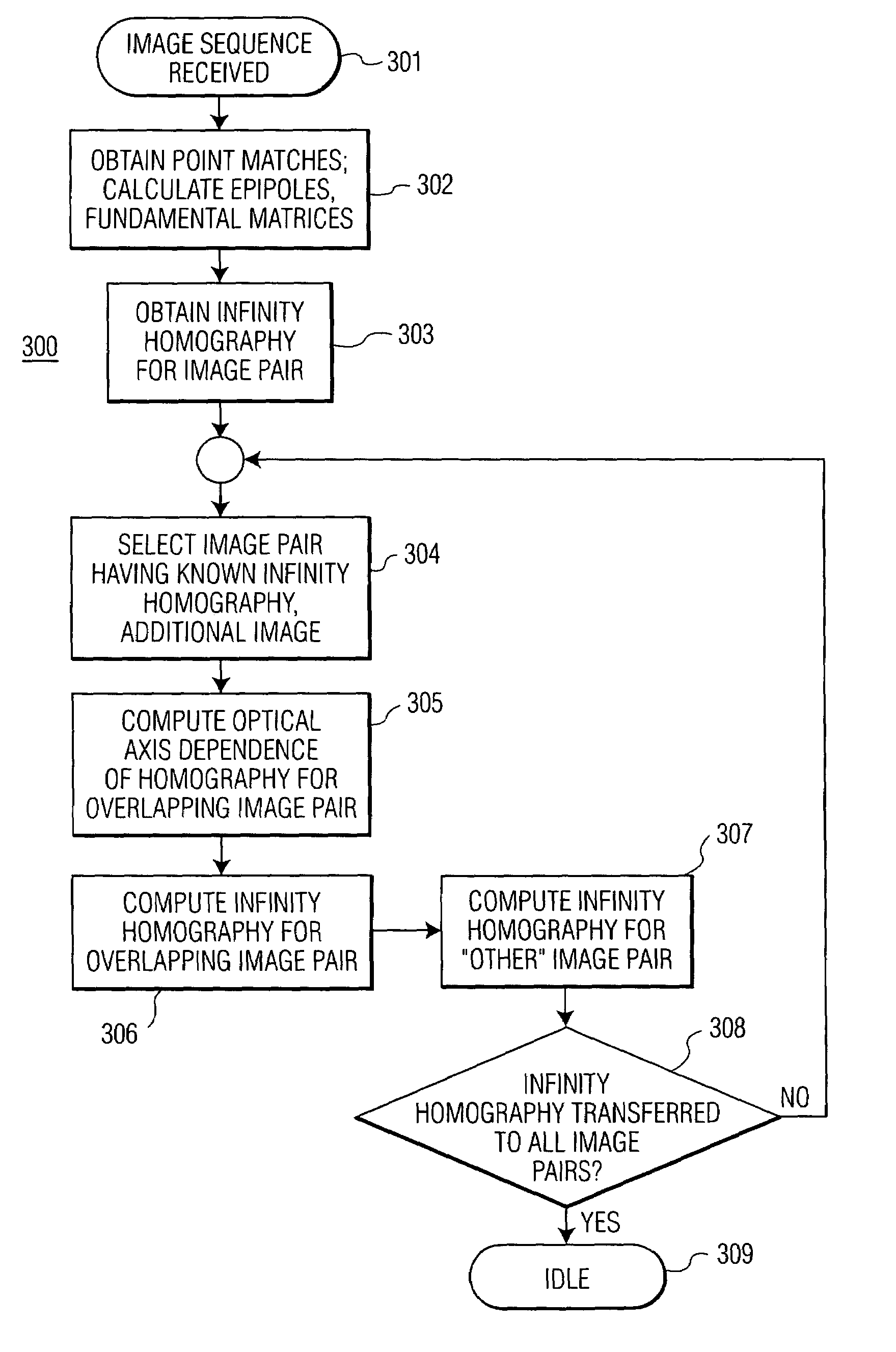
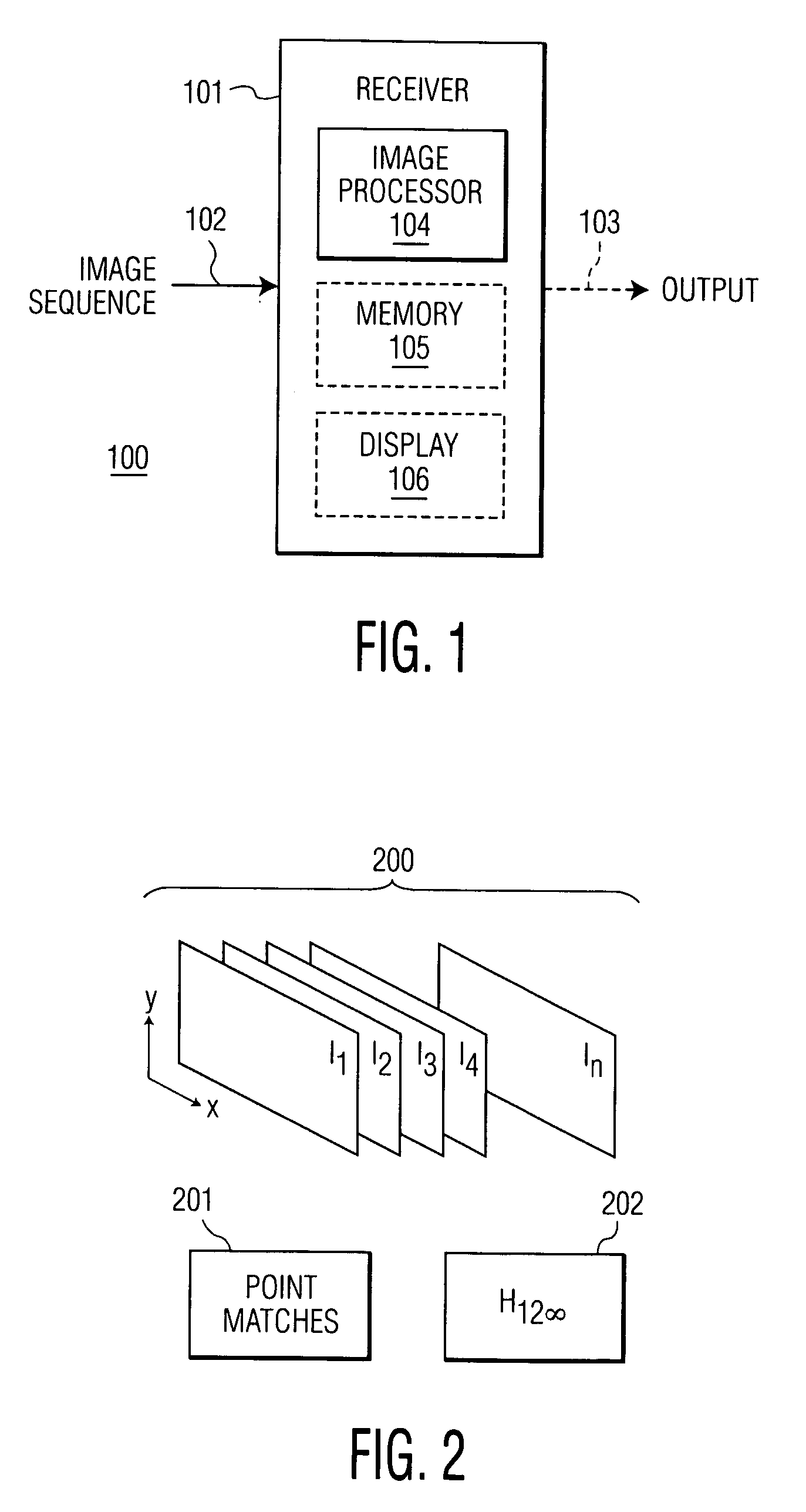
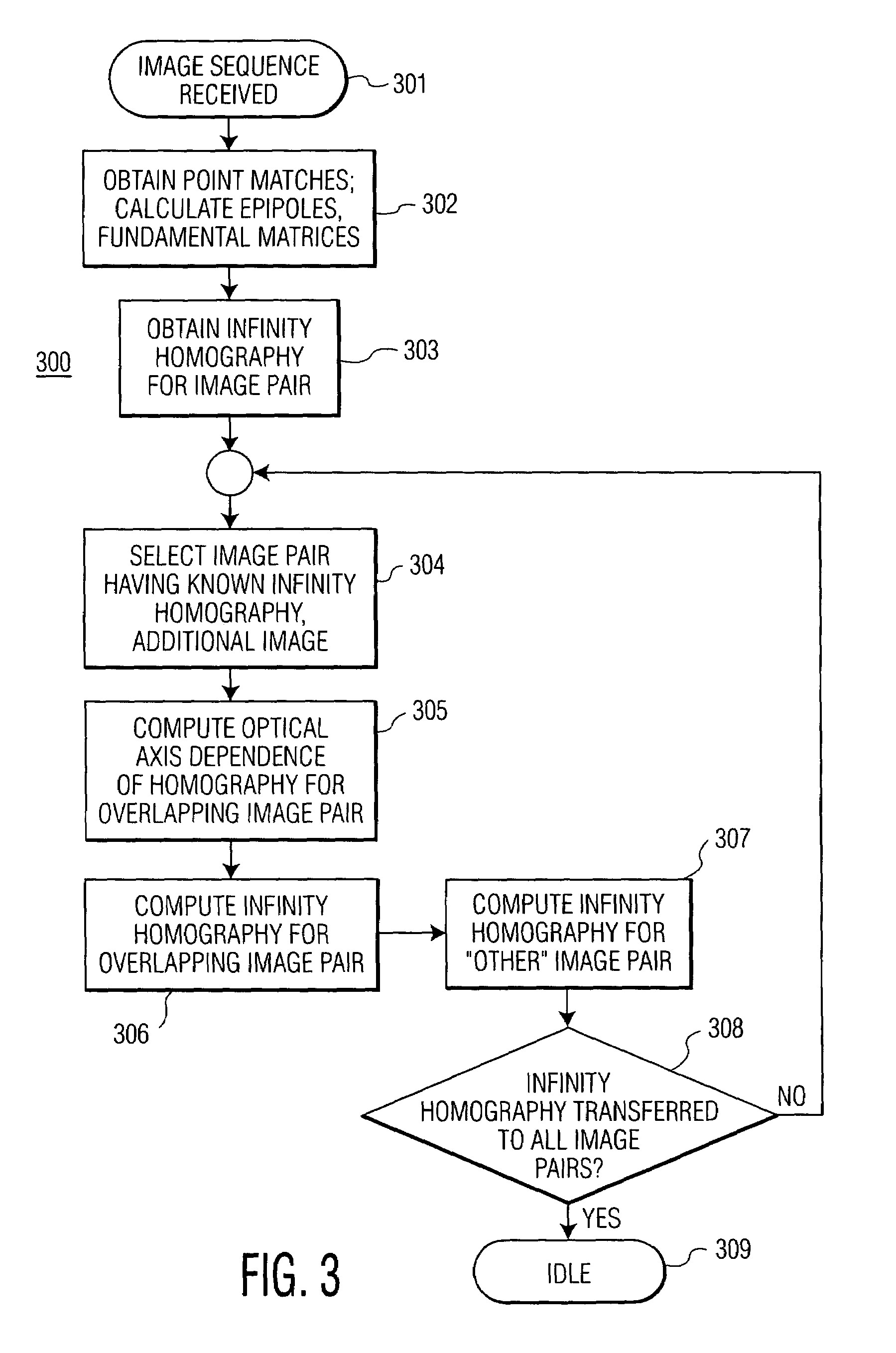
[0015]FIG. 1 depicts a block diagram of a video system employing a method of homography transfer utilizing point matches according to one embodiment of the present invention. Video system 100 includes a video receiver, which may be a computer or other data processing system; a satellite, terrestrial or cable broadcast television receiver; a set top box; or a video game unit. Video receiver 101 has an input 103 for receiving a sequence of images and an optional output 104 for transmitting processed image data to, for example, a display or recording device.

[0016]Video receiver 101 in the exemplar...


PUM


Abstract

An infinity homography for an image pair within an image sequence is transferred to other image pairs within the image sequence utilizing point matches for the subject image pairs. An image set including the image pair for which the infinity homography is known and a third image are selected. Then intermediate parameters for homography transfer for one image pair overlapping the known infinity homography image pair is computed from the known infinity homography and epipoles and fundamental matrices of the overlapping image pairs, to derive the infinity homography for the selected overlapping image pair. The process may then be repeated until infinity homographies for all image pairs of interest within the image sequence have been derived.

Description

TECHNICAL FIELD OF THE INVENTION[0001]The present invention is directed, in general, to view morphing for three dimensional video image generation and, more specifically, to use of homography transfer and epipolar geometry for computing homographies in extended image sequences.BACKGROUND OF THE INVENTION[0002]A homography is a linear projective transformation relating two images for either of two cases: (1) a planar world object projected onto image planes for the two images, where the image planes relate to arbitrary camera motion; or (2) the projection of arbitrary world images onto image planes for pure camera rotation only. A pinhole camera model illustrated in FIG. 4A is employed for the first view to define the location within the camera reference frame (x, y, and z, where z is the optical axis) of an image point m representing the intersection of a line containing a three dimensional world point W and the camera's optical center C with an image plane R. The projection of the ...

Claims


Application Information

Patent Timeline
IPC IPC(8): G06K9/36G06T7/00G06V10/147
CPCG06K9/209G06T7/0075G06K9/6211G06T7/593G06V10/147G06V10/757G06T1/00G06T15/00
Inventor TRAJKOVI, MIROSLAV
Owner UNILOC 2017 LLC
Why Eureka
Try Eureka