Method and apparatus for removing polymeric coatings from optical fiber in a non-oxidizing environment

a technology of optical fiber and polymeric coating, applied in lighting and heating equipment, furnaces, furnace heating elements, etc., can solve the problems of glass fiber, no fiber polymeric coating is completely satisfactory, and no fiber polymeric coating removal method is used

Inactive Publication Date: 2006-02-28
THORLABS INC
View PDF43 Cites 12 Cited by
  • Summary
  • Abstract
  • Description
  • Claims
  • Application Information

AI Technical Summary

Problems solved by technology

Because the surface of the glass fiber is susceptible to damage from abrasion and contamination, the surface is coated with protective polymer immediately after the fiber is drawn.
A variety of approaches have been used to remove fiber polymeric coatings, but none have been completely satisfactory.
This approach inevitably creates surface flaws on the fiber, reducing the strength and the reliability of devices produced from it.
While this approach has been used in manufacturing, it is difficult to automate and involves the use of hazardous chemicals, typically in the form of concentrated acids at high temperatures.

Method used


Image

  • Method and apparatus for removing polymeric coatings from optical fiber in a non-oxidizing environment
  • Method and apparatus for removing polymeric coatings from optical fiber in a non-oxidizing environment
  • Method and apparatus for removing polymeric coatings from optical fiber in a non-oxidizing environment

Examples


Embodiment Construction

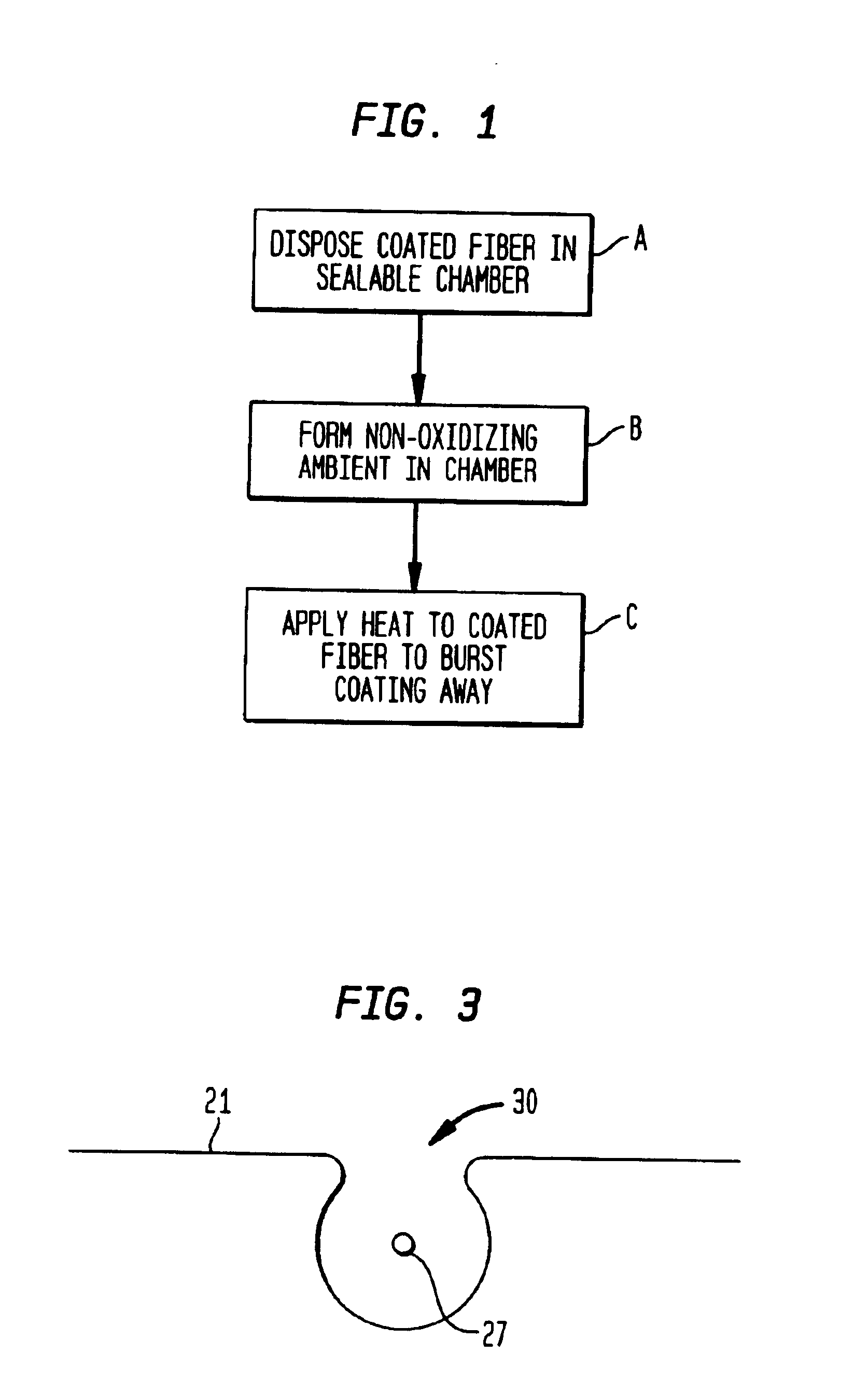
[0012]Referring to the drawings, FIG. 1 is a block diagram of the steps involved in removing a polymeric coating from an optical fiber. The first step shown in block A is to dispose the coated fiber within a sealable chamber.

[0013]The next step (block B) is to form a non-oxidizing environment within the chamber. The chamber can be evacuated to a low pressure and filled with an inert gas such as Argon. The inert gas can be at ambient pressure (e.g. 1 atm) or below.

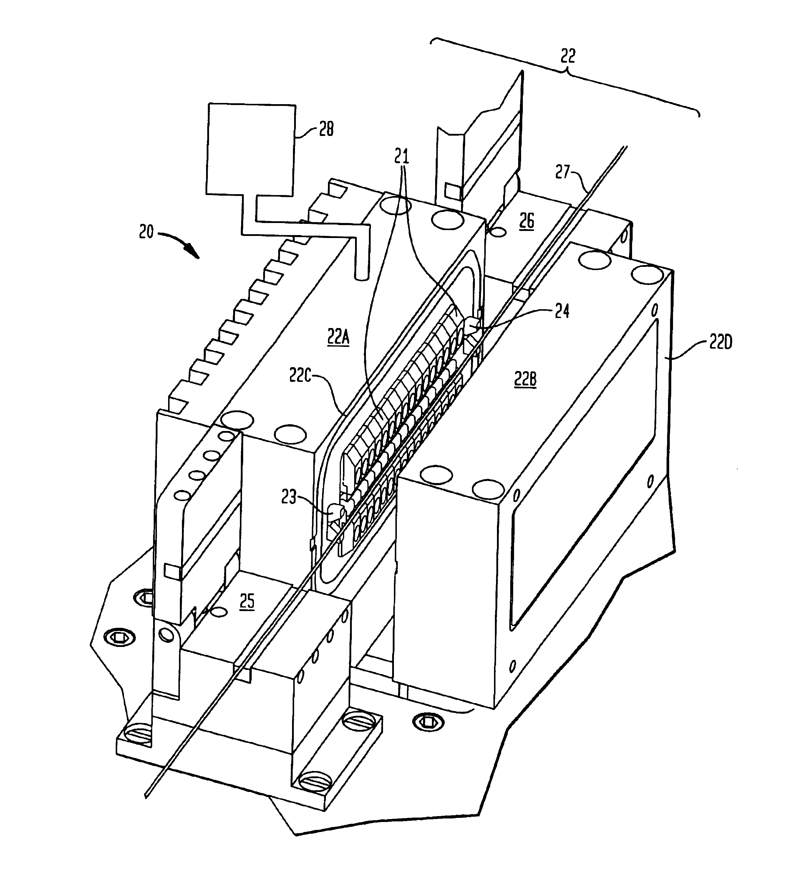
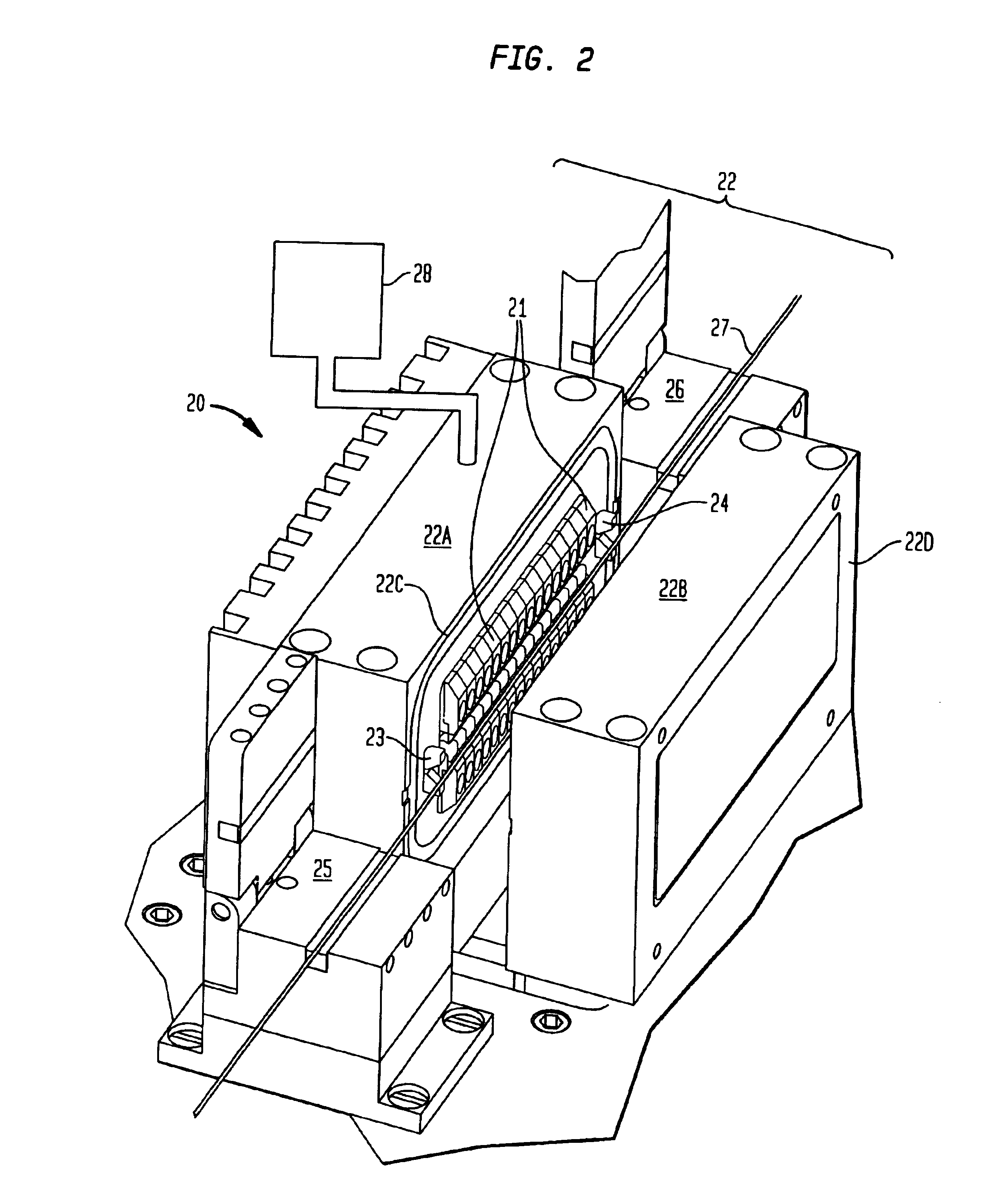
[0014]The third step shown in block C is to apply heat to the coated fiber. The heat should be sufficient to volatilize at least a portion of the coating without changing the phase of the glass. The heat should volatilize at least the most volatile components in the coating and cause the coating to burst from the fiber (explosive removal). The heat is preferably applied from a resistive filament within the evacuated chamber or from a laser, such as an infrared laser, within or outside the chamber. In typical cases involving...


PUM

PropertyMeasurementUnit
temperatureaaaaaaaaaa
pressureaaaaaaaaaa
temperaturesaaaaaaaaaa

Abstract

In accordance with the invention, the polymeric coating is removed from a coated optical fiber by disposing the fiber within a non-oxidizing environment and applying sufficient heat to volatilize at least a portion of the polymeric coating. The result is that the coating material bursts from the fiber, yielding a clean glass surface virtually free of surface flaws. In a preferred embodiment the non-oxidizing environment is inert gas and the heat is provided by resistive filament heaters.

Description

CROSS REFERENCE TO RELATED APPLICATIONS[0001]This application is related to U.S. patent application Ser. No. 09 / 968,211 filed by the present inventors concurrently herewith and entitled “Method and Apparatus For Removing Polymeric Coatings From Optical Fiber”, which is incorporated herein by reference.FIELD OF THE INVENTION[0002]The invention relates to methods for removing polymeric coatings from optical fiber and to apparatus for practicing such methods. In particular it relates to an advantageous method of removing such coatings by the application of heat within a non-oxidizing environment.BACKGROUND OF THE INVENTION[0003]Optical fibers are key components in modem telecommunications systems. Basically, an optical fiber is a thin strand of glass capable of transmitting optical signals containing a large amount of information over long distances with very low loss. In its simplest form, it is a small diameter waveguide comprising a core having a first index of refraction surrounded...

Claims


Application Information

Patent Timeline
Patent Type & Authority Patents(United States)
IPC IPC(8): C03C25/70B08B7/00
CPCC03C25/70Y10S65/09
Inventor SWAIN, ROBERT F.YABLON, ANDREW D.
Owner THORLABS INC
Why Eureka
Try Eureka