Actuating and locking mechanism for a surgical tool

Inactive Publication Date: 2006-02-28
SYCLIX
View PDF15 Cites 117 Cited by
  • Summary
  • Abstract
  • Description
  • Claims
  • Application Information

AI Technical Summary

Benefits of technology

[0016]The locking mechanism therefore provides means for setting the surgical tool in a number of different positions so tha

Problems solved by technology

However, such a mechanism does not provide intermedia

Method used


Image

  • Actuating and locking mechanism for a surgical tool
  • Actuating and locking mechanism for a surgical tool
  • Actuating and locking mechanism for a surgical tool

Examples


Embodiment Construction

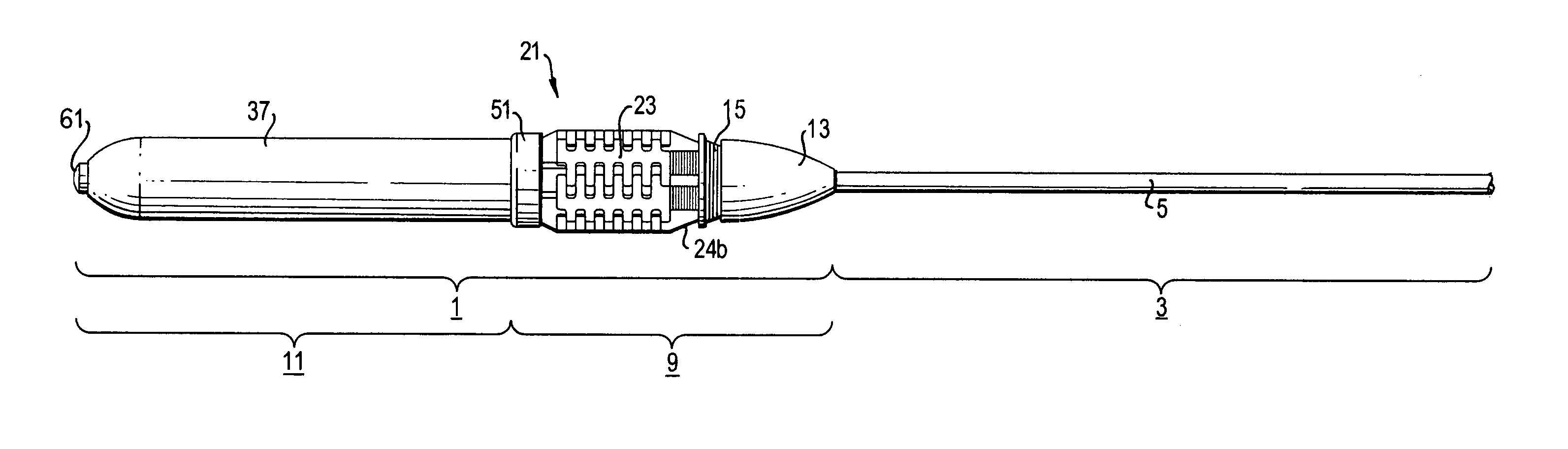
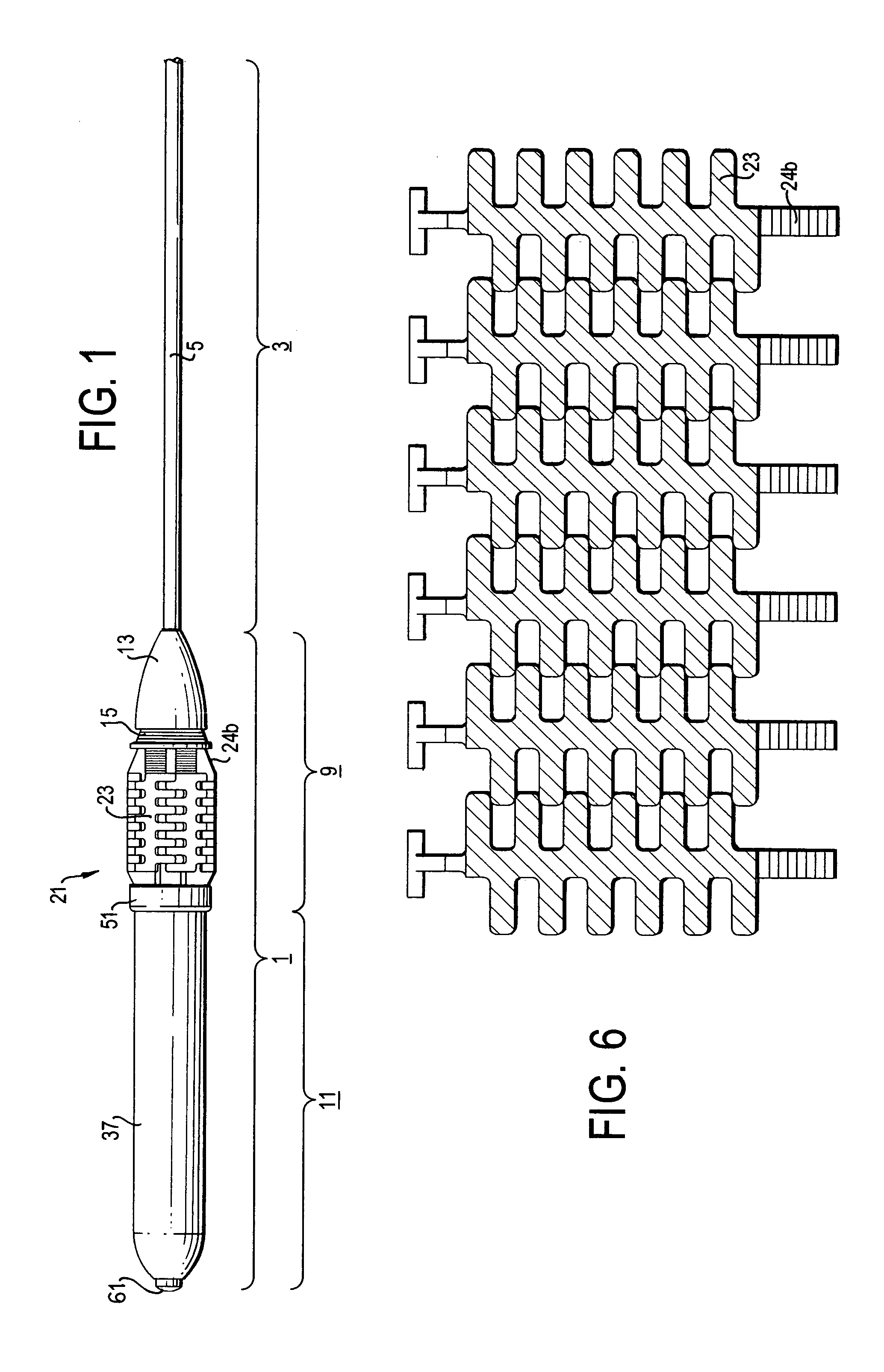
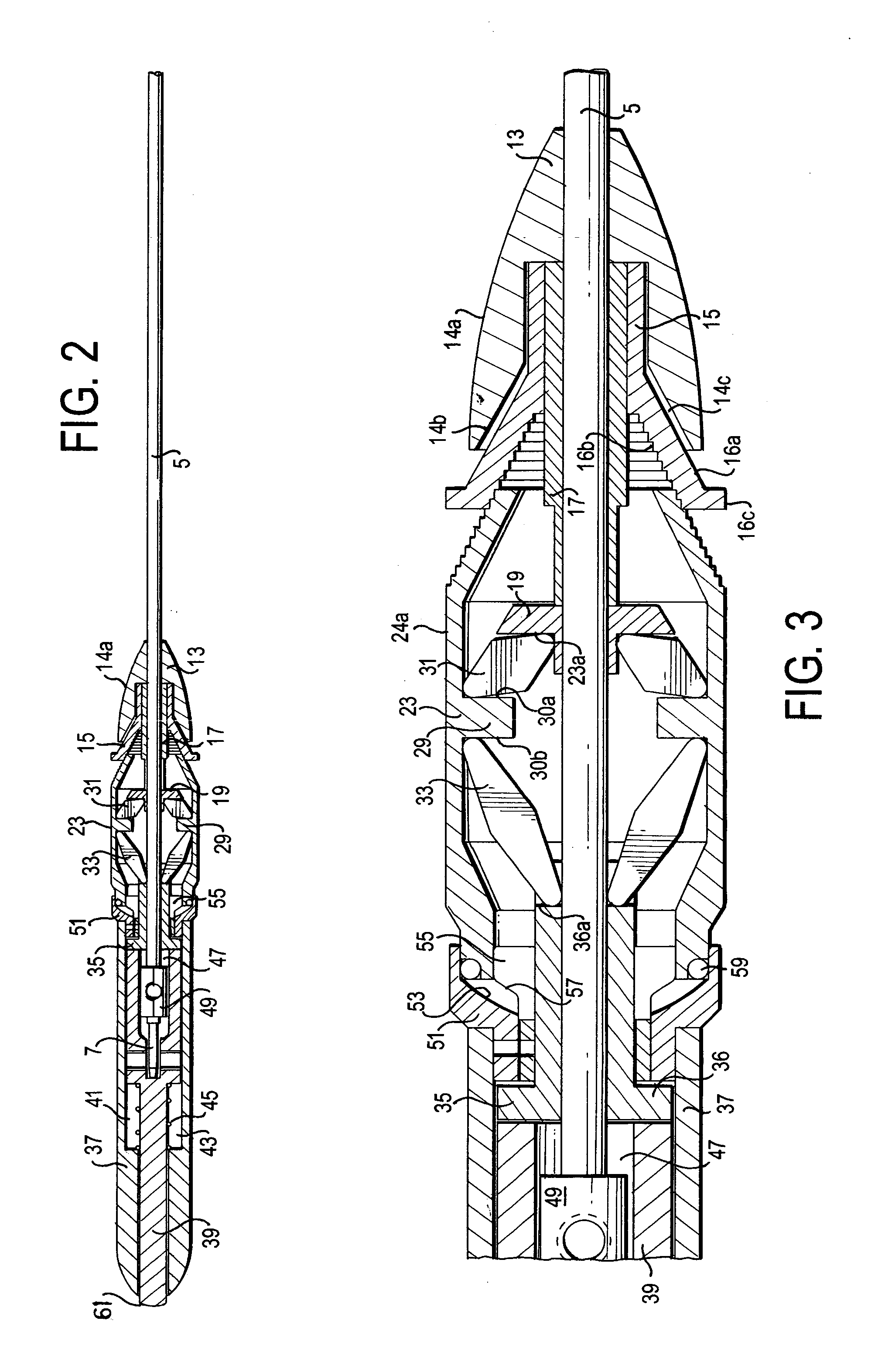
[0036]An embodiment of the present invention will now be described with reference to FIGS. 1 to 7b. The surgical instrument comprises an elongate handle 1 having a shaft 3 extending from one end thereof. A surgical tool or effector (not shown) is mounted at the distal end of the shaft 3. The shaft 3 is of a conventional construction and comprises a hollow outer tube 5 in which is slideably mounted an actuator rod 7. The surgical tool or effector, for example forceps, is actuated by the reciprocal movement of the actuator rod 7 within the outer tube 5.

[0037]The elongate handle 1 comprises an actuator portion 9 which, in use, is grasped between the thumb and forefinger and middle finger in a pen-like grip with the end portion 11 of the handle extending rearwardly between the thumb and forefinger. The actuator 9 comprises a nose portion 13, which has an outer wall 14a which is curved and tapers outwardly towards the end portion 11 of the handle. The nose portion 13 is fixed to the prox...


PUM


Abstract

An actuating mechanism for actuating a surgical tool of a surgical instrument including an actuating device having an actuator surface. The actuating device is operable by applying a force to substantially any part of the actuator surface for placing the actuating device in an actuated position from a rest position for actuating a surgical tool. The actuator surface comprises a radially collapsible cage having a plurality of interdigitating actuating pads. Each pad is movable in a radial direction.

Description

FIELD OF THE INVENTION[0001]The present invention relates to an actuating mechanism for actuating a surgical tool of a surgical instrument. It also relates to a locking mechanism for locking a surgical tool of a surgical instrument.[0002]Minimal invasive surgery, known as key hole surgery, has become increasingly popular. The surgery involves making only a small incision in the patient and inserting a specifically designed implement through the incision. The implement comprises a miniaturised surgical implement such as forceps, clamps, scissors or diathermy hooks at the end of a long shaft with a handle attached to the other end for actuating the implement. The implement is inserted so that the handle is outside of the patient and, therefore the surgeon can operate on the patient through the small incision with minimal invasion. This type of surgery minimises the trauma experienced by the patient, reducing post-operation complications and improving patient's recovery time.[0003]Conv...

Claims


Application Information

Patent Timeline
IPC IPC(8): A61B17/50A61B17/32A61B17/00A61B17/28A61B17/30
CPCA61B17/2909A61B2017/00424A61B2017/2946A61B2017/2918A61B2017/2913
Inventor DAMPNEY, IAN TREVORWICKHAM, JOHN EWANT ALFRED
Owner SYCLIX
Why Eureka
Try Eureka