Apparatus for a welding machine having a cooling assembly mounted to a mid-plane baffle for improved cooling within the welding machine

a technology of cooling assembly and welding machine, which is applied in the field of welding machines, can solve the problems of increasing the overall manufacturing cost of welding machines, difficult to achieve improved cooling efficiency, etc., and achieves the effects of reducing the critical volume of welding machines, dissipating heat within welding machines, and improving cooling efficiency

Inactive Publication Date: 2006-02-28
ILLINOIS TOOL WORKS INC
View PDF13 Cites 10 Cited by
  • Summary
  • Abstract
  • Description
  • Claims
  • Application Information

AI Technical Summary

Benefits of technology

[0007]The present invention solves the aforementioned problems by providing a mid-plane baffle or plate having a fan mounted thereto to dissipate heat within a welding machine. By centrally positioning a baffle and mounting a circulating fan thereto, cooling efficiency is improved thereby enabling more direct cooling of the internal components of the welding machine. The baffle also reduces the critical volume of the welding machine and allows the fan to operate more efficiently and pull an increased amount of cooler ambient air through the machine which creates a greater cooling effect during the cooling cycle of the machine. The baffle placement also improves welding start performance by operating as a barrier between the high frequency / high voltage components and the PC board (control electronics) of the welding machine. The baffle also improves flexibility of component placement within the welding machine.

Problems solved by technology

While the single cavity housing with an external panel mounted fan has adequately dissipated heat generated by the internal welding machine components, improved cooling efficiency is difficult to achieve without an increased size of the fan thereby increasing the overall manufacturing costs of the welding machine.

Method used


Image

  • Apparatus for a welding machine having a cooling assembly mounted to a mid-plane baffle for improved cooling within the welding machine
  • Apparatus for a welding machine having a cooling assembly mounted to a mid-plane baffle for improved cooling within the welding machine
  • Apparatus for a welding machine having a cooling assembly mounted to a mid-plane baffle for improved cooling within the welding machine

Examples


Embodiment Construction

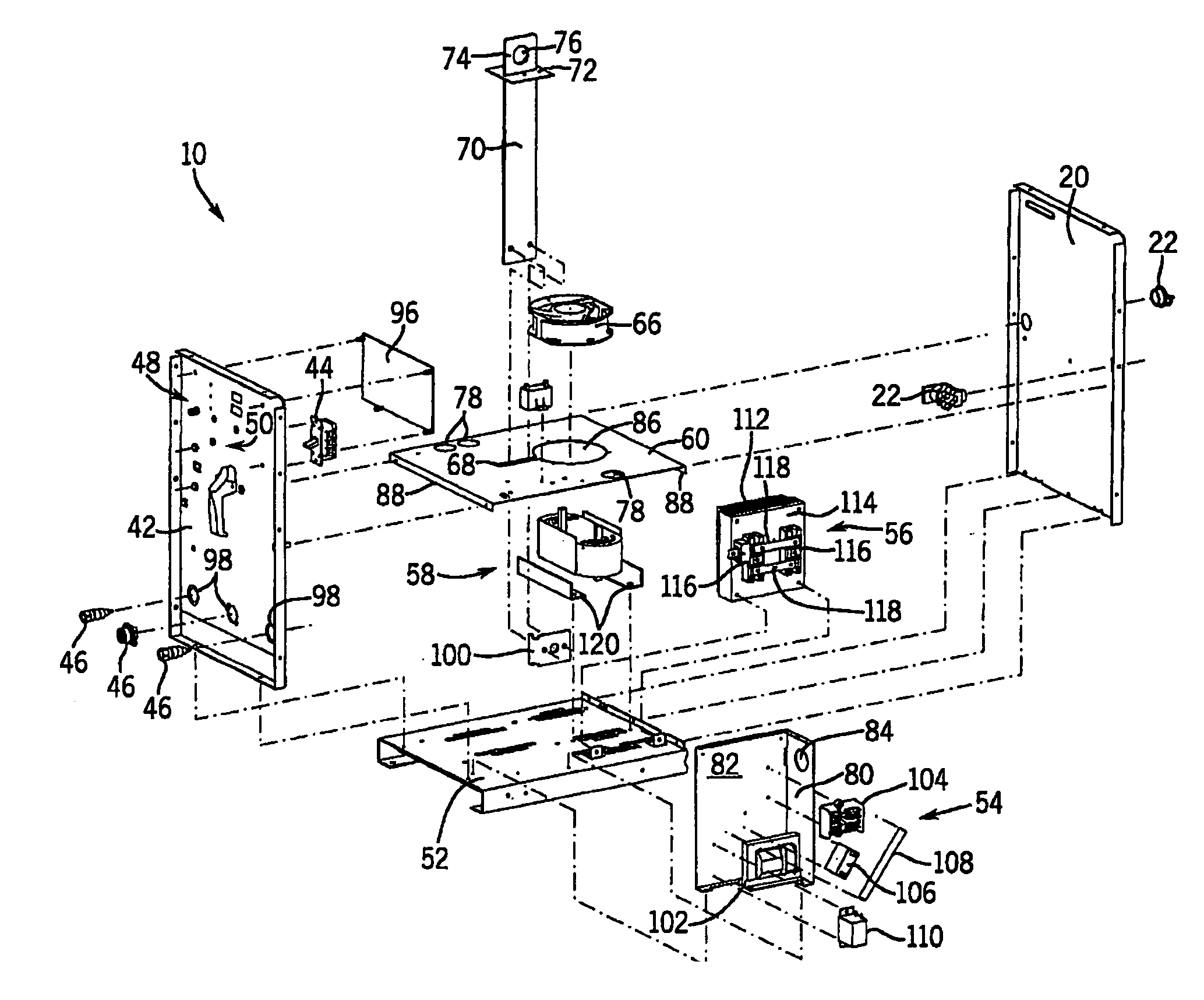
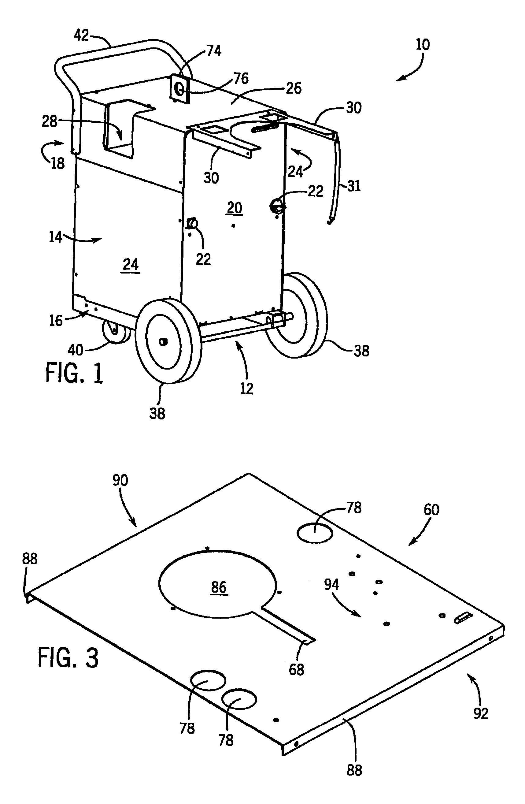
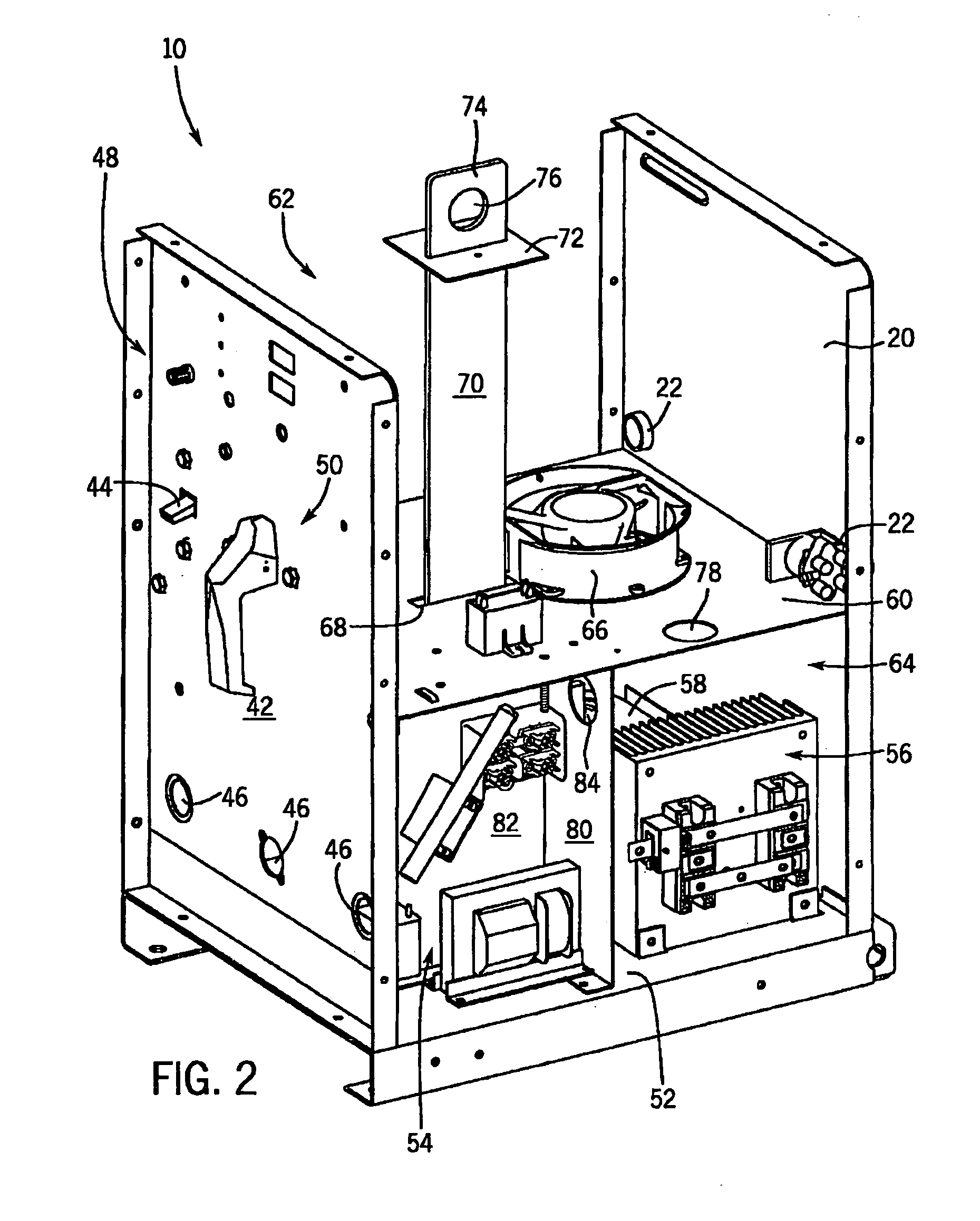
[0019]FIG. 1 is a perspective view of a welding machine 10, incorporating in one embodiment, a retractable rack assembly 12. The welding machine 10 comprises a housing 14 having a base 16, and a plurality of panels spaced apart from one another and extending upwardly from the base 16. The plurality of panels includes a front panel 18 with control knobs and switches (not shown), a back panel 20 with control knobs and / or valves 22 and a pair of side panels 24. A top cover 26 is secured to the panels that collectively enclose the internal components of the welding machine 10. The top cover 26 has an opening 28 to allow access to the interior of the housing 14. Panels 20, 24 and top cover 26 are preferably fabricated from blank sheet metal as is well known in the art. A pair of support bars 30 extend outwardly from housing 14 and a strap 31 to support an upper portion of a gas cylinder (not shown). The retractable rack assembly 12 supports the body of a gas cylinder when extended outwar...


PUM

PropertyMeasurementUnit
internal volumeaaaaaaaaaa
volumeaaaaaaaaaa
volumesaaaaaaaaaa

Abstract

A mid-plane baffle or plate having a fan mounted thereto to dissipate heat within a welding machine is provided. By centrally positioning a baffle and mounting a circulating fan thereto, cooling efficiency is improved thereby enabling more direct cooling of the internal components of the welding machine. The baffle also reduces the critical volume of the welding machine and allows the fan to operate more efficiently and pull an increased amount of cooler ambient air through the machine which creates a greater cooling effect during the cooling cycle of the machine. The baffle placement also improves welding start performance by operating as a barrier between the high frequency/high voltage components and the PC board (control electronics) of the welding machine. The baffle also improves flexibility of component placement within the welding machine.

Description

CROSS REFERENCE TO RELATED APPLICATION[0001]The present invention is a continuation and claims the benefit and priority of U.S. Ser. No. 10 / 063,816 filed May 15, 2002, now U.S. Pat. No. 6,803,541, the disclosure of which is incorporated herein.BACKGROUND OF THE INVENTION[0002]The present invention relates generally to welding machines and, more particularly, to a welding machine having a mid-plane baffle for improved heat dissipation / cooling of the welding machine.[0003]There are a large number of welding processes available for use in the industry. The most common welding processes include gas tungsten arc, oxygen gas welding, and shielded metal arc welding. The gas tungsten arc welding process is sometimes referred to as TIG (tungsten inert gas) welding. TIG welding is commonly performed by a TIG welding machine utilizing an inert gas.[0004]A typical TIG welding machine includes a transformer, stabilizer and various electrical components that convert the input power into power sui...

Claims


Application Information

Patent Timeline
Patent Type & Authority Patents(United States)
IPC IPC(8): B23K9/067B23K9/10B23K9/32B23K37/00
CPCB23K9/10B23K9/1006H05K7/20909B23K37/003B23K9/32
Inventor ANDERSEN, BRYAN P.WERBA, DAVID A.
Owner ILLINOIS TOOL WORKS INC
Why Eureka
Try Eureka