Method and apparatus for accurate alignment of images in digital imaging systems by matching points in the images corresponding to scene elements

Inactive Publication Date: 2006-02-28
COGENETENS
View PDF7 Cites 4 Cited by
  • Summary
  • Abstract
  • Description
  • Claims
  • Application Information

AI Technical Summary

Benefits of technology

[0008]In brief summary, the invention provides a new digital imaging system and method that facilitates the location of anchors or targets in images of a scene. The invention provides two general aspects. In one general aspect, the digital imaging system makes use of, for example, differences as between the properties of the surfaces of the targets and the properties of the surfaces of the objects that are to be mensurated, reconstructed, etc., to facilitate providing uniform illumination of the targets when recording a set of images of the scene, thereby reducing noise that may arise in connection with determining the locations of the targets if they were illuminated by structured illumination, while contemporaneously providing that the objects can be illuminated by structured illumination when the images are recorded. In this aspect, the digital imaging system can use the positions of the targets in the images to relate a local coordinate system associated with the image set to a global coordinate system.

Problems solved by technology

Since the imaging system will need to make a quick and accurate identification of the targets, several problems can arise.
However, if the imaging system requires structured illumination, which provides a textured appearance for surfaces that what might otherwise appear relatively featureless, the simultaneous use of structured illumination and uniform illumination will typically reduce-the effect of the structured illumination on the scene, which, in turn, can interfere with the imaging system's ability to perform its mensuration, virtual reconstruction, and so forth, operations.
On the other hand, if structured lighting is used alone or predominately to illuminate the scene, including the targets, the appearance of respective ones of the targets can change from image to image, which will make it more difficult for the imaging system to identify the projections of a respective in the various images.
In addition, the structured illumination can cause projections of the targets to appear deformed, which can increase the difficulty of accurately determining their locations in the images.
Finally, if both structured lighting and uniform illumination are used, but for recording of successive images from what is hoped to be the same direction, problems can arise since one or both of the camera or other device that records the images and the object(s), including the target(s), in the scene can vibrate or otherwise move, which, in turn, can cause inaccuracies in registration between the two images.
The time interval between times at which the camera can record successive images can vary based on a number of variables, including, for example, image size and resolution, image buffer download time, and so forth, but often the time interval is long enough for such differences to have adverse effects.
This can significantly reduce the accuracy of the mensuration, reconstruction, and / or other operations that the imaging system may be required to perform.

Method used


Image

  • Method and apparatus for accurate alignment of images in digital imaging systems by matching points in the images corresponding to scene elements
  • Method and apparatus for accurate alignment of images in digital imaging systems by matching points in the images corresponding to scene elements
  • Method and apparatus for accurate alignment of images in digital imaging systems by matching points in the images corresponding to scene elements

Examples


Embodiment Construction

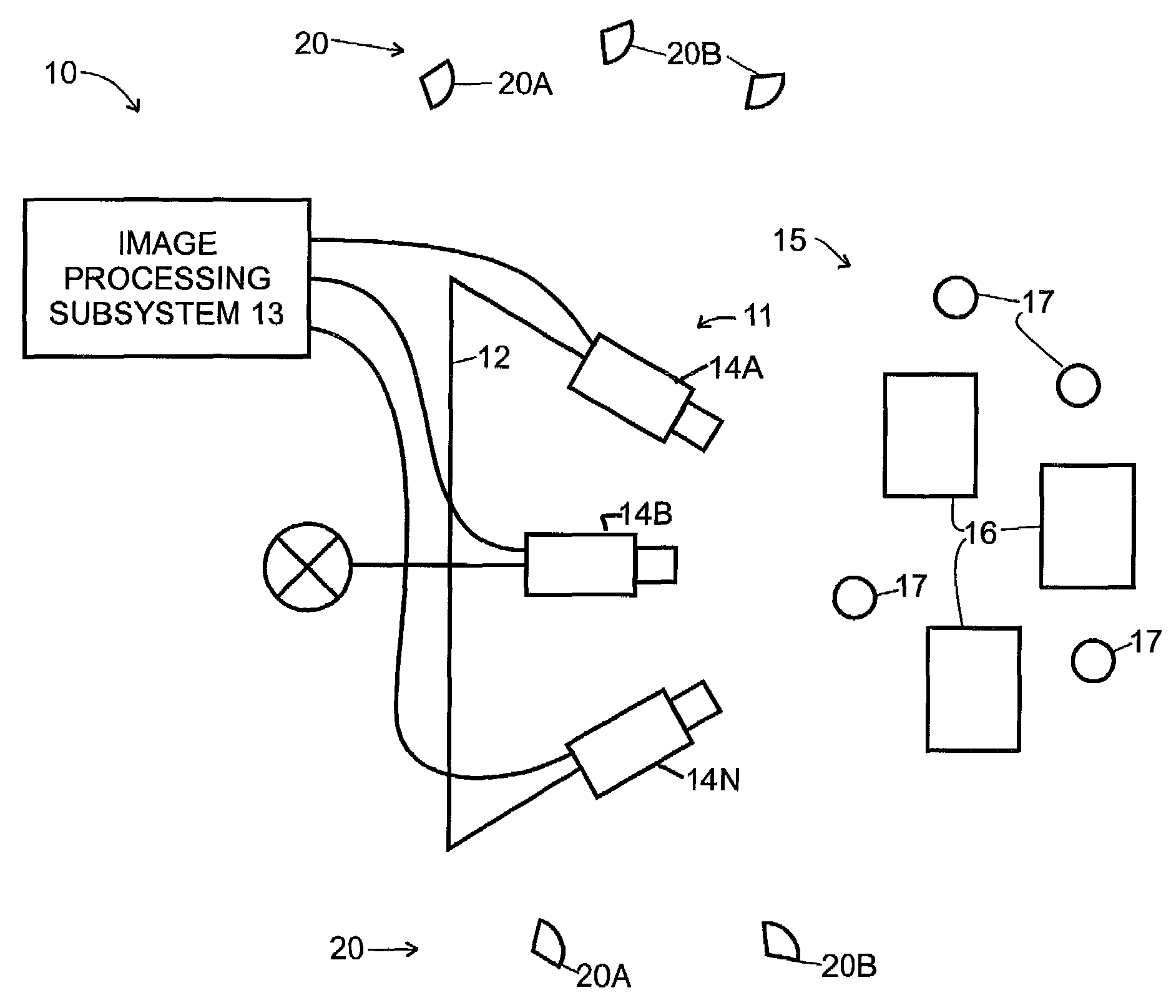
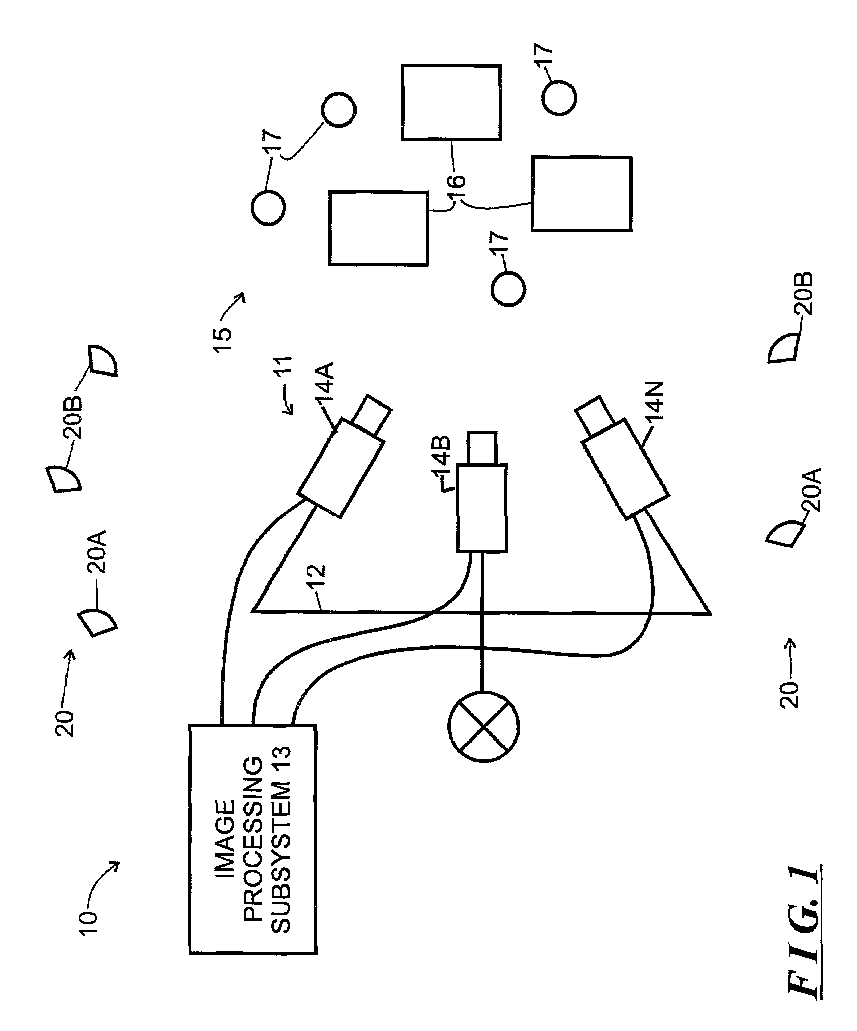
[0014]FIG. 1 schematically depicts a digital imaging system 10 constructed in accordance with the invention. The digital imaging system 10 includes an optical head 11, a rig 12, and image processing subsystem 13. The optical head 11 comprises one or more cameras 14A, . . . , 14N (generally identified by reference numeral 14n) each of which can record images of a scene 15. The rig 12 is provided with a motion capability, for example, that can translate and / or rotate the optical head 11 relative to the scene 15 to allow the cameras 14n comprising the optical head 11 to record sets of images of the scene 15 from a plurality of positions and angular orientations. In one embodiment, the cameras 14n comprising the optical head 11 include image sensing and recording media such as CCD (charge coupled devices) or CMOS (complementary metal-oxide semiconductor) devices, which record images in electronic form, and the cameras 14n download the images to the image processing subsystem 13 after th...


PUM


Abstract

A digital imaging system is described that facilitates the location of anchors or targets in images of a scene. In one aspect, the digital imaging system makes use of differences as between the properties of the surfaces of the targets and the properties of the surfaces of the objects that are to be mensurated, reconstructed, etc., to facilitate providing uniform illumination of the targets when recording a set of images of the scene, thereby reducing noise that may arise in connection with determining the locations of the targets if they were illuminated by structured illumination, while contemporaneously providing that the objects can be illuminated by structured illumination when the images are recorded. In this aspect, the digital imaging system can use the positions of the targets in the images to relate a local coordinate system associated with the image set to a global coordinate system. In a second aspect, the digital imaging system makes use of one or more of a plurality of algorithms to determine the locations of targets in the images of the scene in the respective objects. In this aspect, the digital imaging system records two sets of images, including a baseline set and a working set. The baseline set is recorded using uniform illumination, with the baseline set comprising only images of the targets. The working set is recorded using structured illumination, with the working set comprising image of both the targets and the objects. The working set is used in connection with mensuration, virtual reconstruction, etc., and one or more of the algorithms are used to determine the likely positions of the targets in the images in the working image set, and to determine transformations between the baseline and working image set such that the local coordinate system associated with the working image set can be related to the global coordinate system.

Description

FIELD OF THE INVENTION[0001]The invention relates generally to the field of digital imaging, and more particularly to systems and methods for aligning images in digital imaging systems.BACKGROUND OF THE INVENTION[0002]Digital imaging systems record many images of a scene for various applications. Some applications require accurate knowledge of the positions of points in the scene, in relation to a three-dimensional coordinate system, which, in turn, requires accurate knowledge of the locations of projections of the points in the respective images. One illustrative application is photogrammetry, in which information such as distances between points in a scene, heights of points in the scene above a reference level, and so forth, can be determined from measurements between and among points on the two-dimensional images that were recorded of the scene. Another application is three-dimensional virtual reconstruction of objects in a scene from the two-dimensional images that were recorde...

Claims


Application Information

Patent Timeline
IPC IPC(8): G09G5/00G06T15/00G01B11/00G01C11/00G06T1/00G06T7/00
CPCG01C11/00G06T7/0077G06T7/0057G06T7/521G06T7/596
Inventor ALBECK, DANGERSHON, RONSEGEV, AVNER
Owner COGENETENS
Why Eureka
Try Eureka