
Method and system for MPEG chroma de-interlacing

a chroma deinterlacing and chroma line technology, applied in the field of video signal processing, can solve the problems of further degradation of the chroma vertical resolution, and achieve the effect of reversing the step of increasing the chroma line and increasing the number of chroma lines

Inactive Publication Date: 2006-02-28
INTERDIGITAL MADISON PATENT HLDG
View PDF34 Cites 31 Cited by
  • Summary
  • Abstract
  • Description
  • Claims
  • Application Information

AI Technical Summary

Benefits of technology

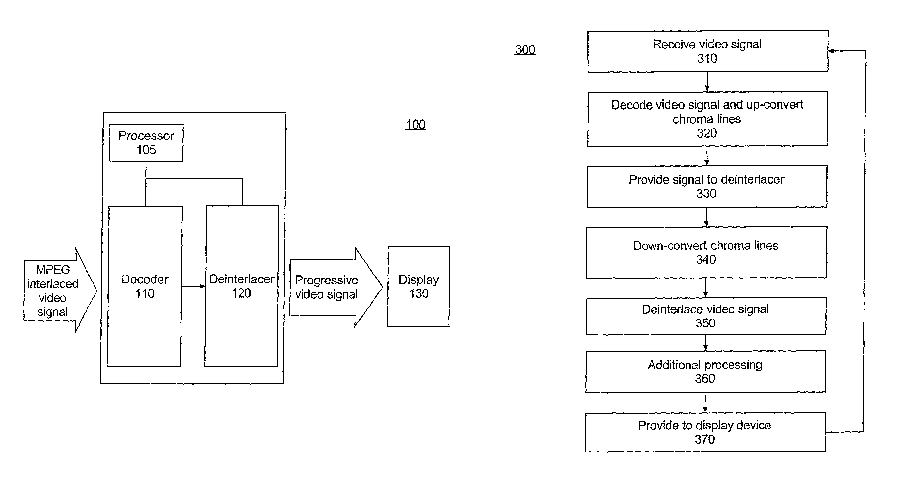
[0009]One aspect of the present invention can include a method of converting interlaced video signals to progressive video signals. The method can include receiving an interlaced video signal representing a luma component specifying luma lines and a chroma component specifying chroma lines. The chroma component can specify approximately one-half the number of lines of the luma component. The interlaced video signal can be decoded and the number of chroma lines can be increased to approximately the same as the number of the luma lines. The number of chroma lines of the interlaced video signal can be decreased back to approximately one-half of the number of the luma lines, thereby substantially reversing the step of increasing the chroma lines. The interlaced video signal then can be deinterlaced. Accordingly, the deinterlacing can result in a progressive video signal representing a luma component specifying luma lines and a chroma component specifying chroma lines. The progressive video signal can be processed further as necessary.

Problems solved by technology

This can result in further degradation of the chroma vertical resolution.

Method used


Image

  • Method and system for MPEG chroma de-interlacing
  • Method and system for MPEG chroma de-interlacing
  • Method and system for MPEG chroma de-interlacing

Examples


Embodiment Construction

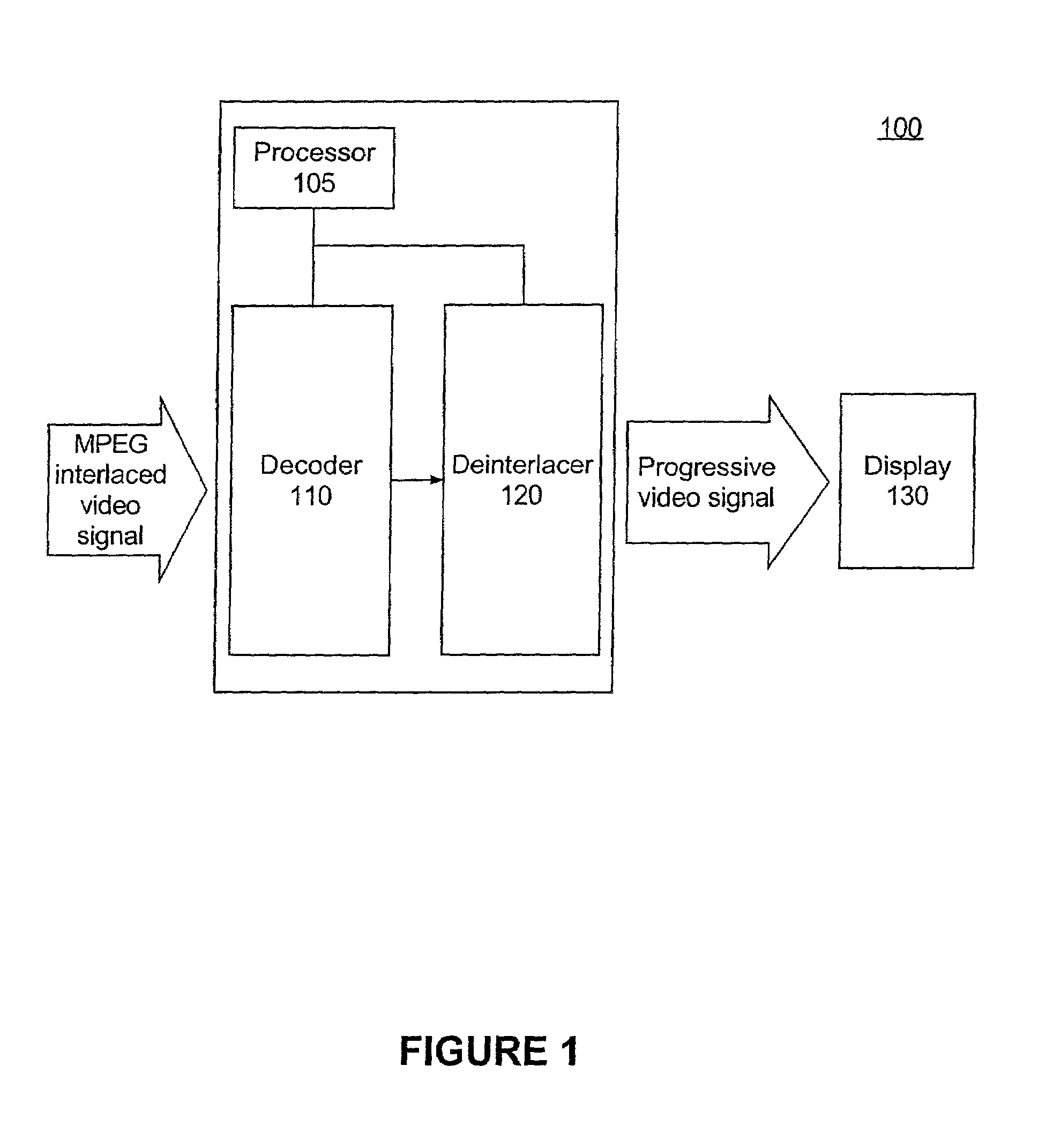
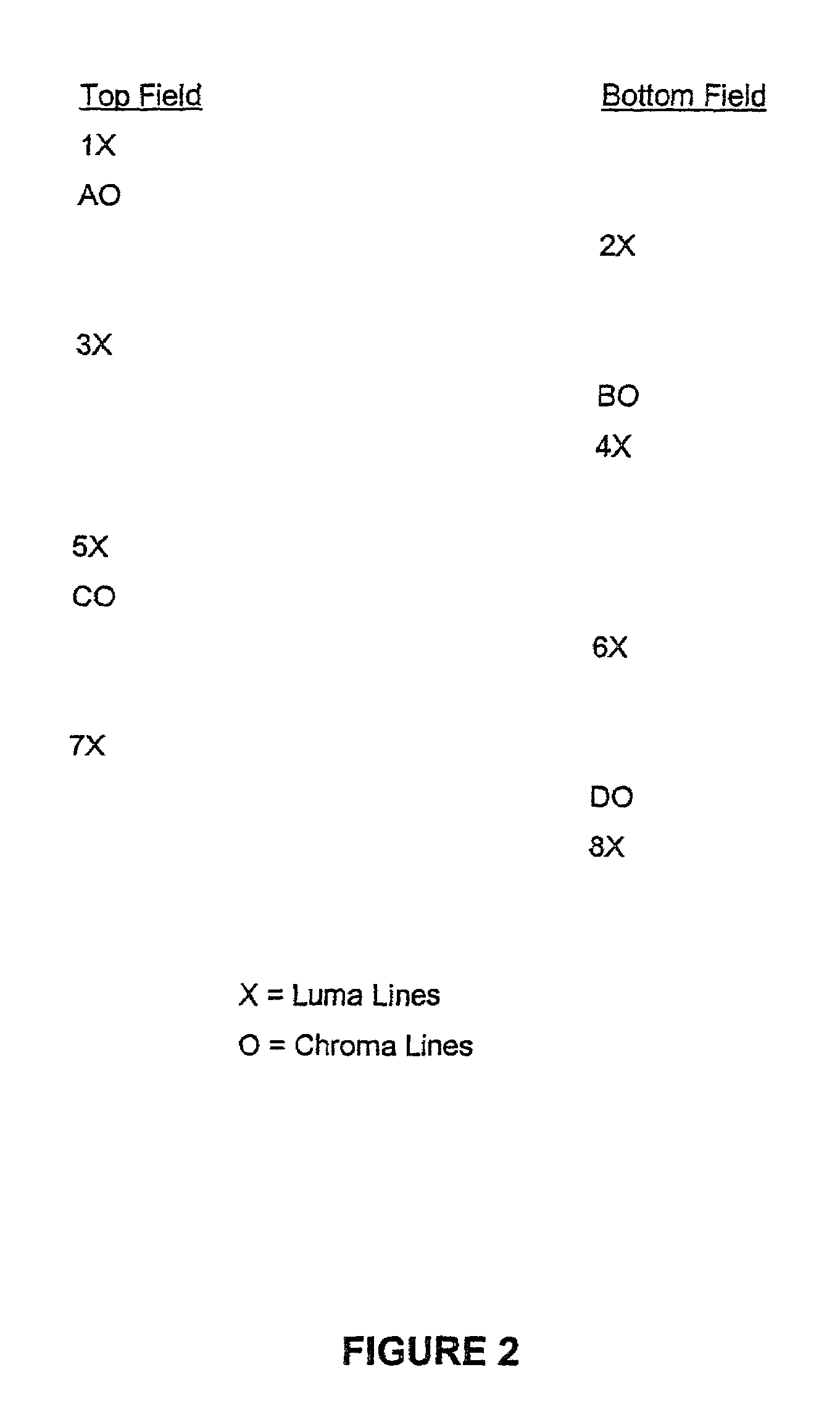
[0021]The invention disclosed herein provides a method and system for deinterlacing and vertically format converting an interlaced Moving Picture Experts Group (MPEG) video signal. In accordance with the inventive arrangements disclosed herein, the interlaced video signal is deinterlaced prior to vertically expanding the chroma component of the interlaced video signal. Accordingly, the invention retains a high degree of vertical resolution for the chroma component (which is, at most, 50% of the luma vertical resolution) when performing deinterlacing and chroma vertical format conversions.

[0022]FIG. 1 is a schematic diagram illustrating an exemplary system 100 for converting interlaced video formats to progressive video formats. As shown in FIG. 1, the system 100 can include an MPEG 2 video decoder module (decoder) 110, an interlace to progressive video processing system (deinterlacer) 120, and a processor 105. The decoder 110 can decode and convert a received, interlaced 4:2:0 forma...


PUM


Abstract

A method (300) of converting interlaced Moving Picture Experts Group (MPEG) video signals to progressive video signals can include receiving an interlaced video signal representing a luma component specifying luma lines and a chroma component specifying chroma lines (310) wherein the chroma component can specify approximately one-half the number of lines of the luma component. The interlaced video signal can be decoded and the number of the chroma lines can be increased to approximately the same as the number of the luma lines (320). The number of chroma lines of the interlaced video signal then can be decreased (340), to substantially reverse the previous increase. The interlaced video signal then can be deinterlaced to produce a progressive video signal (350), which can be processed further (360) as needed.

Description

CROSS-REFERENCE TO RELATED APPLICATIONS[0001]This application claims the benefit of U.S. Provisional Application No. 60 / 257,723 which was filed Dec. 22, 2000 and 60 / 259,531 which was filed Jan. 3, 2001, in the United States Patent and Trademark Office.BACKGROUND OF THE INVENTION[0002]1. Technical Field[0003]The present invention relates to the processing of video signals, and more particularly, to the conversion of interlaced video formats into progressive video-formats known as deinterlacing.[0004]2. Description of the Related Art[0005]Presently, many of the transmitted and broadcast TV signals are interlaced. Many of these signals are transmitted in Moving Picture Experts Group (MPEG) form. For example, the Advanced Television Systems Committee (ATSC) has developed the standard for digital television wherein the signals, referred to as ATSC signals, are transmitted in MPEG form. Some of the ATSC formats are interlaced, for example 480i and 1080i video signals. These MPEG signals a...

Claims


Application Information

Patent Timeline
IPC IPC(8): H04N7/01H04N11/20G06T9/00H04N5/44H04N5/66H04N9/64H04N21/4402
CPCG06T9/007H04N5/4401H04N21/440218H04N7/0135H04N7/012H04N5/66H04N9/64H04N21/426H04N7/01
Inventor WILLIS, DONALD HENRY
Owner INTERDIGITAL MADISON PATENT HLDG
Learn More