Apparatus and method for attaching a heat sink to an integrated circuit module

a heat sink and integrated circuit technology, applied in the direction of cooling/ventilation/heating modification, semiconductor/solid-state device details, semiconductor devices, etc., can solve the problems of significant clip mounting space, cracking of silicon, and significant fragility of the silicon structure to which the heat sink is bonded, so as to limit the resulting compression of thermally conductive materials and limit the flexure of the substrate

Active Publication Date: 2006-02-28
INT BUSINESS MASCH CORP
View PDF12 Cites 30 Cited by
  • Summary
  • Abstract
  • Description
  • Claims
  • Application Information

AI Technical Summary

Benefits of technology

[0011]The circuit board assembly may also include a compression limiting structure, limiting the shrinkage of the shrink curable adhesive during the curing process to limit the resulting compression of the thermally conductive material and to limit flexure of the substrate. The compression limiting structure extends between the annular portion of the outer surface of the substrate and the annular portion of the inner surface of the heat sink, extending outward from the substrate or inward from the heat sink.

Problems solved by technology

However, as the circuit chips grow smaller, and as the heat sinks required to dissipate increasing levels of power grow larger, the fragility of the silicon structure to which the heat sink is bonded becomes a significant problem.
In particular, a massive heat sink can cause cracking of the silicon due to mechanical shock and vibration.
However, the use of an external spring clip typically requires the existence of significant clip mounting space outside the footprint of the circuit chip.
Such space is becoming increasingly difficult to provide, as it is becoming necessary to provide increased levels of function in smaller sections of a circuit board.

Method used


Image

  • Apparatus and method for attaching a heat sink to an integrated circuit module
  • Apparatus and method for attaching a heat sink to an integrated circuit module
  • Apparatus and method for attaching a heat sink to an integrated circuit module

Examples


Embodiment Construction

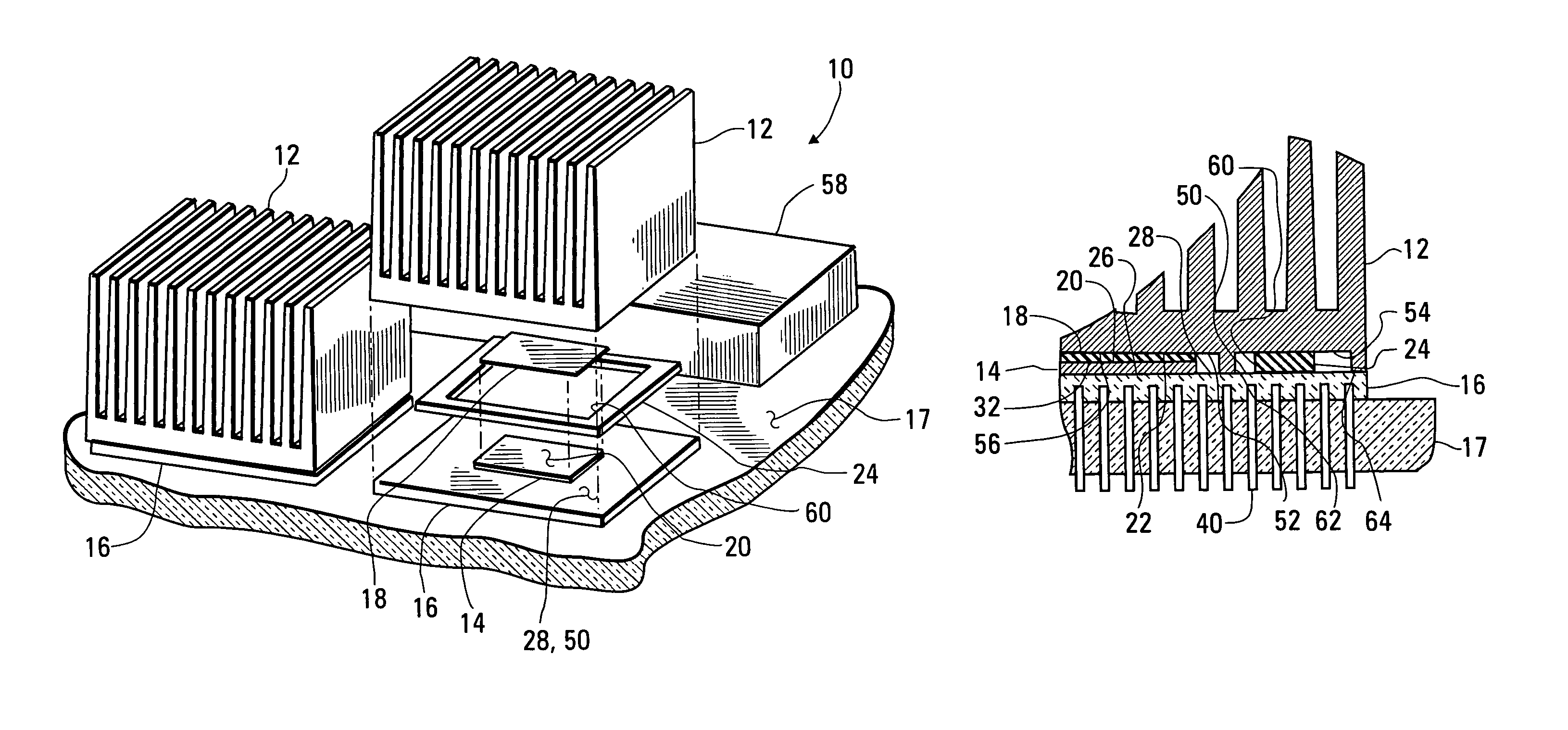
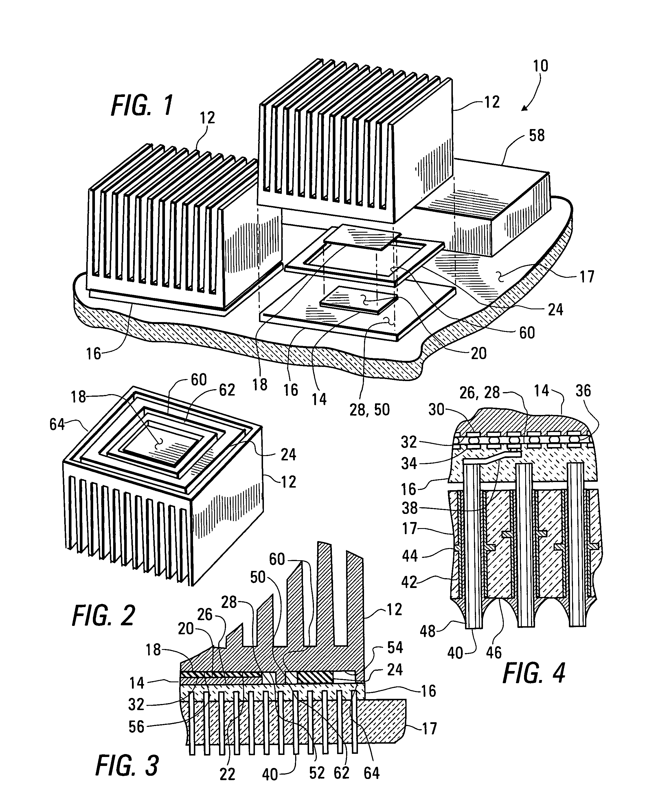
[0027]A first version of the invention will now be discussed, with reference being made to FIGS. 1–3. FIG. 1 is a fragmentary perspective view of a circuit board assembly 10 built in accordance with a first version of the invention, including a number of heat sinks 12 attached to extend over a number of circuit chips 14 and associated substrates 16, which are in turn attached to a circuit board 17. A circuit chip 14 and an associated substrate 16 together form an integrated circuit module. One of the heat sinks 12 is shown in an exploded relationship with other elements of the circuit board assembly 10. FIG. 2 is a perspective view of a heat sink 12 in an inverted orientation, shown as prepared for attachment within the circuit board assembly 10. FIG. 3 is a fragmentary vertical cross-sectional view of the circuit board assembly 10, showing the attachment of a heat sink 12 to a substrate 16.

[0028]Thermal conduction between each of the circuit chips 14 and an associated heat sink 12 ...


PUM


Abstract

A heat sink is fastened to an annular portion of a substrate of an integrated circuit module on a printed circuit card by means of a cured layer of cure shrinkable adhesive. A circuit chip is soldered to a central portion of the substrate, around which the annular portion extends. A layer of thermally conductive material is placed between the circuit chip and a central portion of the heat sink, to be compressed as the layer of cure shrinkable adhesive is cured. A compression limiting structure may additionally extend between the heat sink and the annular portion of the substrate, limiting the shrinkage of the adhesive and thus the compression of the thermally conductive material and the flexure of the substrate.

Description

BACKGROUND OF THE INVENTION[0001]1. Field of the Invention[0002]This invention relates to the manufacture of integrated circuit modules and of circuit boards including integrated circuit modules, and, more particularly, to the attachment of heat sinks to integrated circuit modules within circuit board assemblies.[0003]2. Summary of the Background Art[0004]Due to decreases in the size of circuit elements, such as transistors within integrated circuit modules, and additionally due to increases in the clock frequencies used within computing systems, integrated circuits are being built in smaller sizes with increased levels of capability, often resulting in increased levels of heat generation. This statement is particularly true for the chips supporting controllers in personal computer. Such support chips are now being designed to dissipate significantly more power than similar devices from previous generations of circuits. Additionally, more powerful support chips are being designed wi...

Claims


Application Information

Patent Timeline
Patent Type & Authority Patents(United States)
IPC IPC(8): H05K7/20
CPCH01L23/42H01L24/73H01L24/83H01L24/92H01L23/49811H01L2924/12041H01L2924/0665H01L2924/014H01L2924/01043H01L2924/01033H01L2924/01005H01L2224/2919H01L2224/131H01L2224/92225H01L2224/839H01L23/49827H01L24/81H01L2224/29099H01L2224/73253H01L2224/81815H01L2924/00014H01L2924/01014H01L2924/00H01L2924/3512H01L2224/05026H01L2224/05573H01L2924/14H01L2224/05599
Inventor MATTESON, JASON AARON
Owner INT BUSINESS MASCH CORP
Why Eureka
Try Eureka