Apparatus and methods for verifying the location of areas of interest within a sample in an imaging system
- Summary
- Abstract
- Description
- Claims
- Application Information
AI Technical Summary
Benefits of technology
Problems solved by technology
Method used
Image
Examples
Embodiment Construction
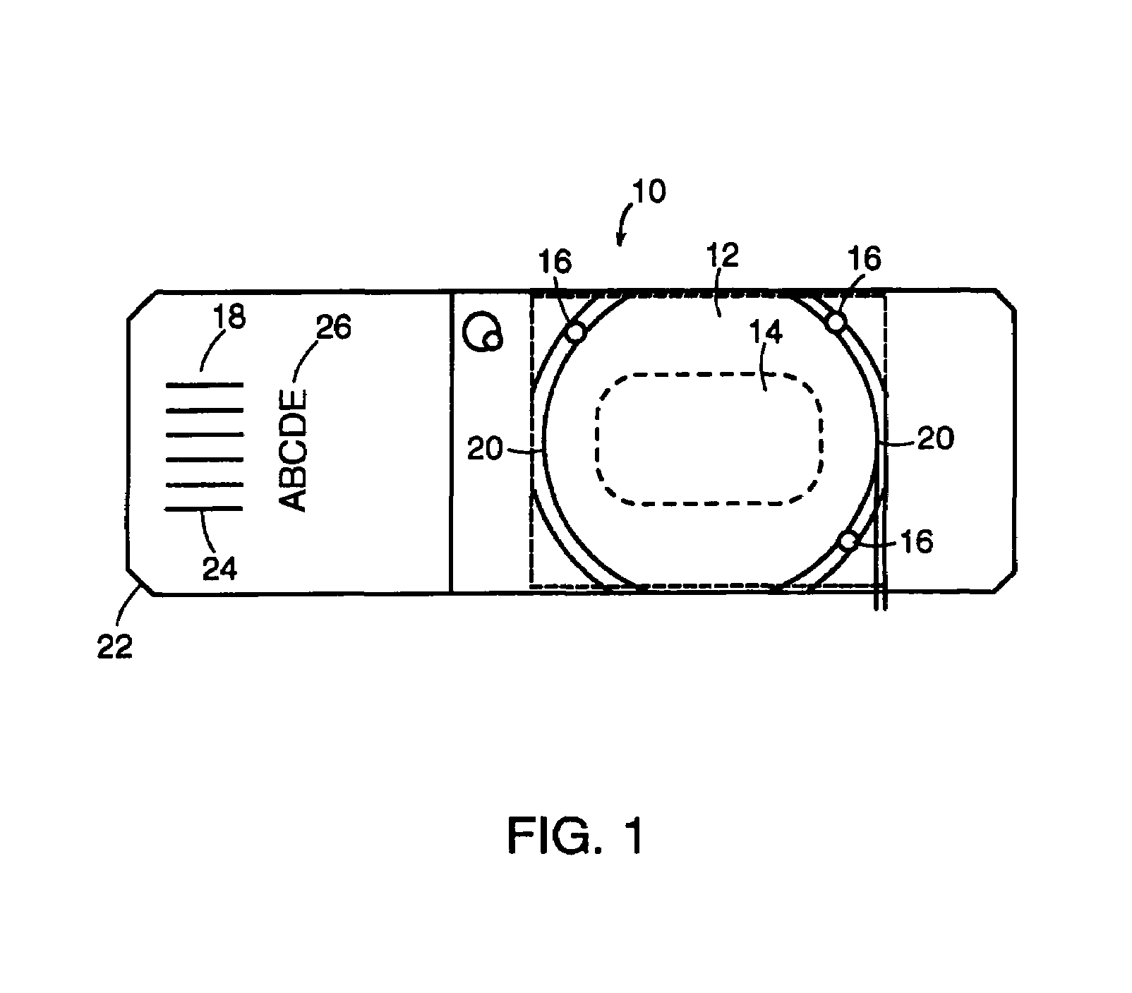
[0019]FIG. 1 is a top view of a microscope slide 10 of the present invention. The slide 10 has a specimen area 12 adapted for the deposition of a sample, such as a cytological specimen 14, thereon. The slide 10 has toleranced dimensions and chamfered edges to facilitate handling and use of the slide 10 in automated calibrated equipment, such as imaging equipment. In one embodiment, the slide 10 is manufactured from glass and has a width of about one inch, a length of about three inches, and a thickness of about 0.04 inches.
[0020]The slide 10 has at least one datum mark 16 placed thereon, and may have two or more marks 16 placed thereon. The specimen area 12 may be bounded, at least in part by two marks 16. The mark 16 which may be referred to alternatively as a fiducial mark, is visible in a field of view of an optical instrument such as a microscope or a camera of an imaging system, and can be used as a reference datum or for measurement calibration purposes. In one embodiment, the...
PUM
 Abstract
Description
Claims
Application Information
 - R&D
- Intellectual Property
- Life Sciences
- Materials
- Tech Scout
- Unparalleled Data Quality
- Higher Quality Content
- 60% Fewer Hallucinations
Browse by: Latest US Patents, China's latest patents, Technical Efficacy Thesaurus, Application Domain, Technology Topic, Popular Technical Reports.
© 2025 PatSnap. All rights reserved.Legal|Privacy policy|Modern Slavery Act Transparency Statement|Sitemap|About US| Contact US: help@patsnap.com


