Method and apparatus for low cost signature testing for analog and RF circuits

a low-cost signature and circuit technology, applied in the field of low-cost signature testing for analog and rf circuits, can solve the problems of imposing an increasing burden on traditional testing methods in the form of test time, neither is applicable to non-linear circuits, nor provides quantitative information about circuit performance parameters themselves, etc., to achieve efficient reduction of test time and therefore cost, and low cost

Inactive Publication Date: 2006-02-28
GEORGIA TECH RES CORP
View PDF4 Cites 36 Cited by
  • Summary
  • Abstract
  • Description
  • Claims
  • Application Information

AI Technical Summary

Benefits of technology

[0010]The method and apparatus for low cost signature testing for analog and RF circuits according to the present invention solves the aforementioned problems and meets the aforementioned needs by providing a model adapted to predict one or more performance parameters characterizing a first electronic circuit produced by a manufacturing process subject to process variation from the output of one or more second electronic circuits produced by the same process in response to a selected test stimulus, and iteratively varying the test stimulus to minimize the error between the predicted performance parameters and corresponding measured values for the performance parameters, for determining an optimized test stimulus.
[0012]Therefore, it is a principal object of the present invention to provide a novel and improved method and apparatus for low cost signature testing for analog and RF circuits.
[0013]It is another object of the invention to provide such a novel and improved method and apparatus for low cost signature testing for analog and RF circuits that efficiently reduces test time and therefore cost.
[0014]It is yet another object of the invention to provide such a novel and improved method and apparatus that provides for maximizing prediction accuracy.
[0015]It is still another object of the present invention to provide such a method and apparatus for low cost signature testing for analog and RF circuits that provides more information about circuit performance parameters than would otherwise be available.
[0016]It is a further object of the present invention to provide such a method and apparatus for low cost signature testing for analog and RF circuits that provides for calibrating for short or long term variations in the manufacturing process.

Problems solved by technology

However, traditional testing methods impose an increasing burden in the form of test time as a result of the ever increasing complexity and speeds of analog and RF circuits.
Some serious drawbacks of these methods are that neither is applicable to non-linear circuits, and neither provides quantitative information about the circuit performance parameters themselves.
Further the method of the latter reference places a demand on the user to provide a set of test stimuli, hence the method provides no assistance in generating or optimizing the test stimuli.
Moreover, an additional problem encountered in testing RF circuits is the need for very high frequencies in the test signal.
This imposes an additional cost on testing, as the ATE needed to produce high frequency test signals of arbitrary shape is more complex and difficult to use.
Neither of the aforementioned prior art test methodologies has addressed this problem.

Method used


Image

  • Method and apparatus for low cost signature testing for analog and RF circuits
  • Method and apparatus for low cost signature testing for analog and RF circuits
  • Method and apparatus for low cost signature testing for analog and RF circuits

Examples


Embodiment Construction

[0024]The present application incorporates herein by reference that portion of the U.S. provisional application Ser. No. 60 / 197,749, entitled “Test Generation for Accurate Prediction of Analog Specifications,” which provides mathematical explanation, background and support for methods according to the invention that are described herein in a simplified manner. Also incorporated herein is the inventor's paper, submitted to the International Test Conference 2001, entitled “Low-Cost Signature Testing of RF Circuits,” attached hereto as Appendix A.

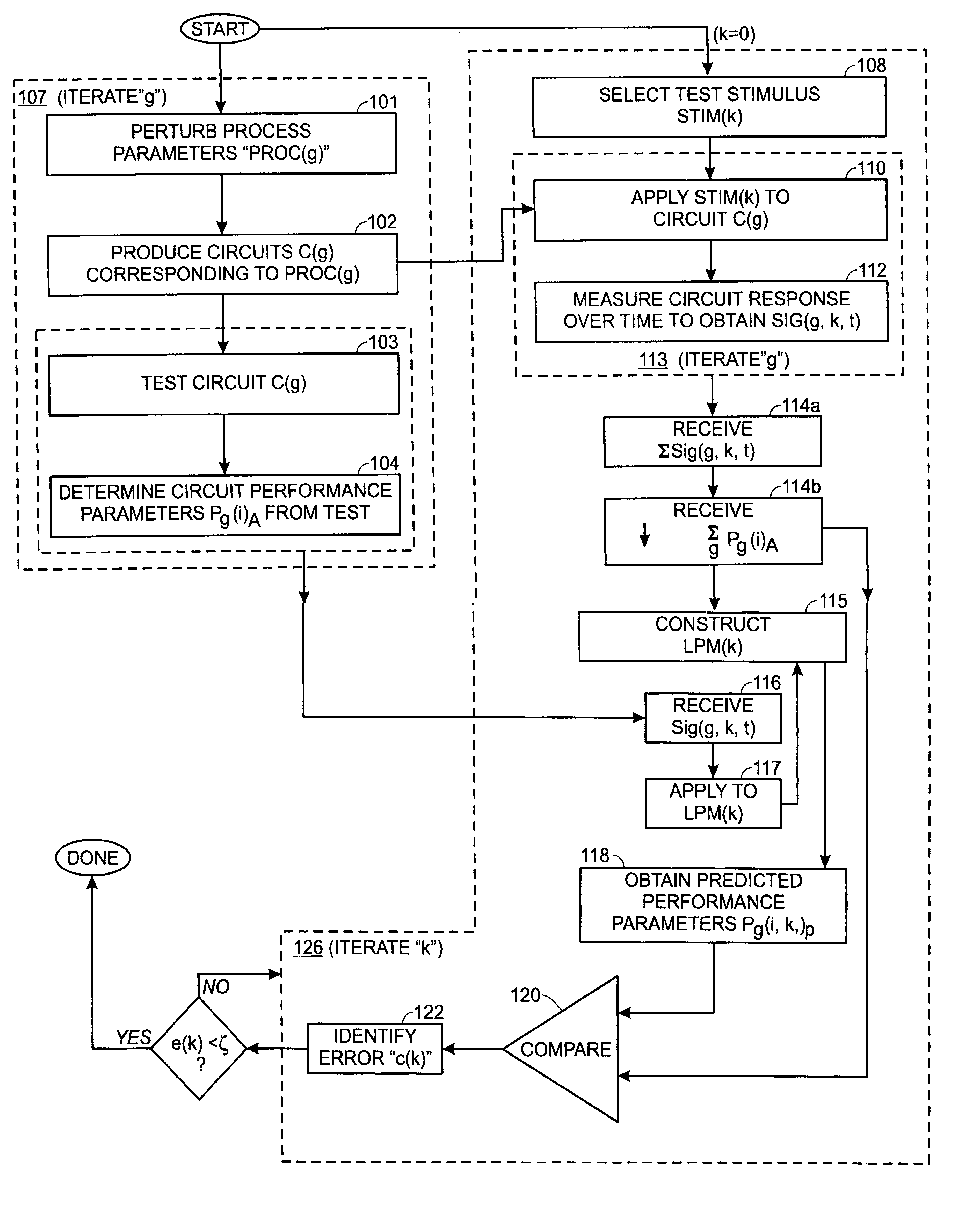
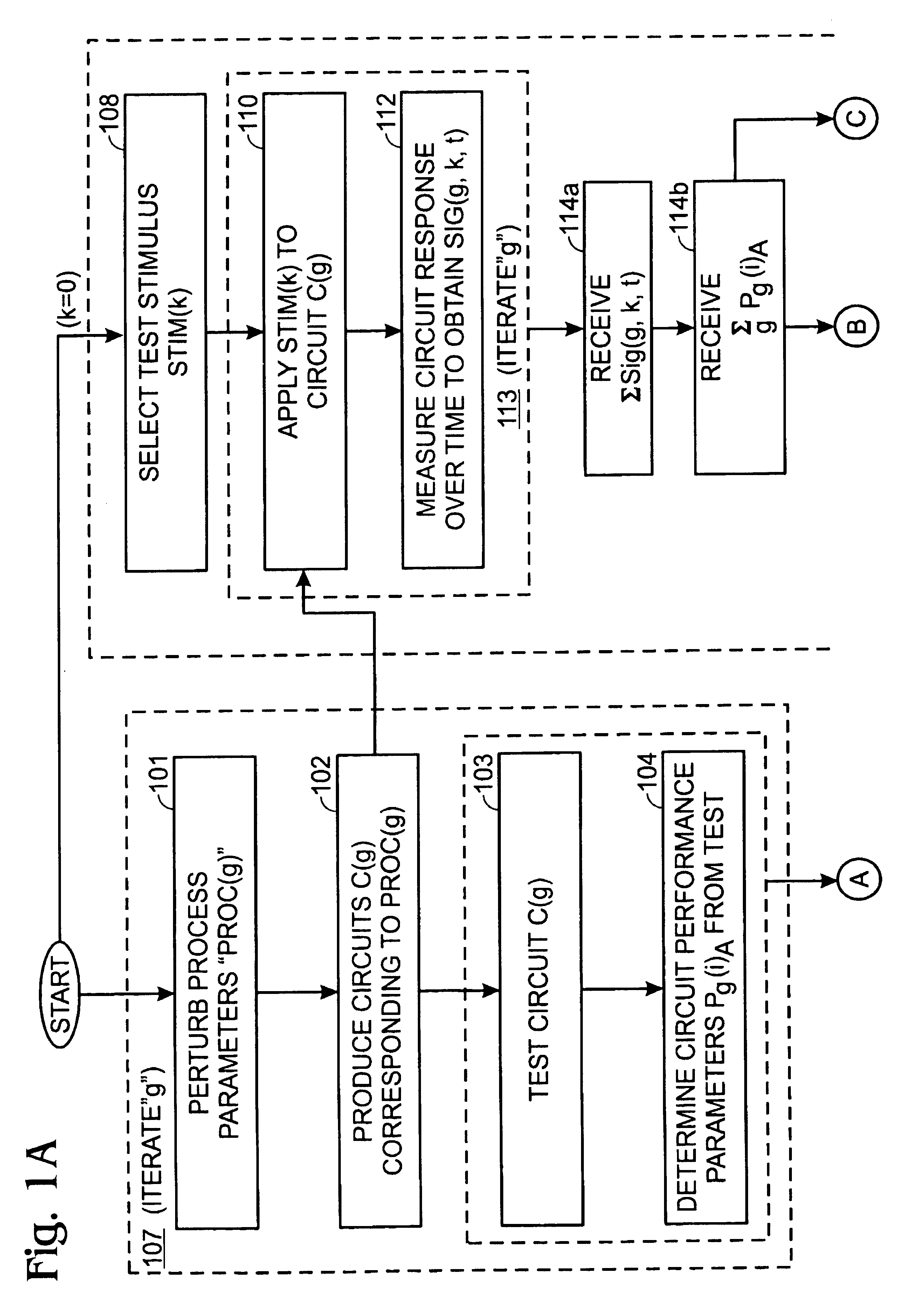
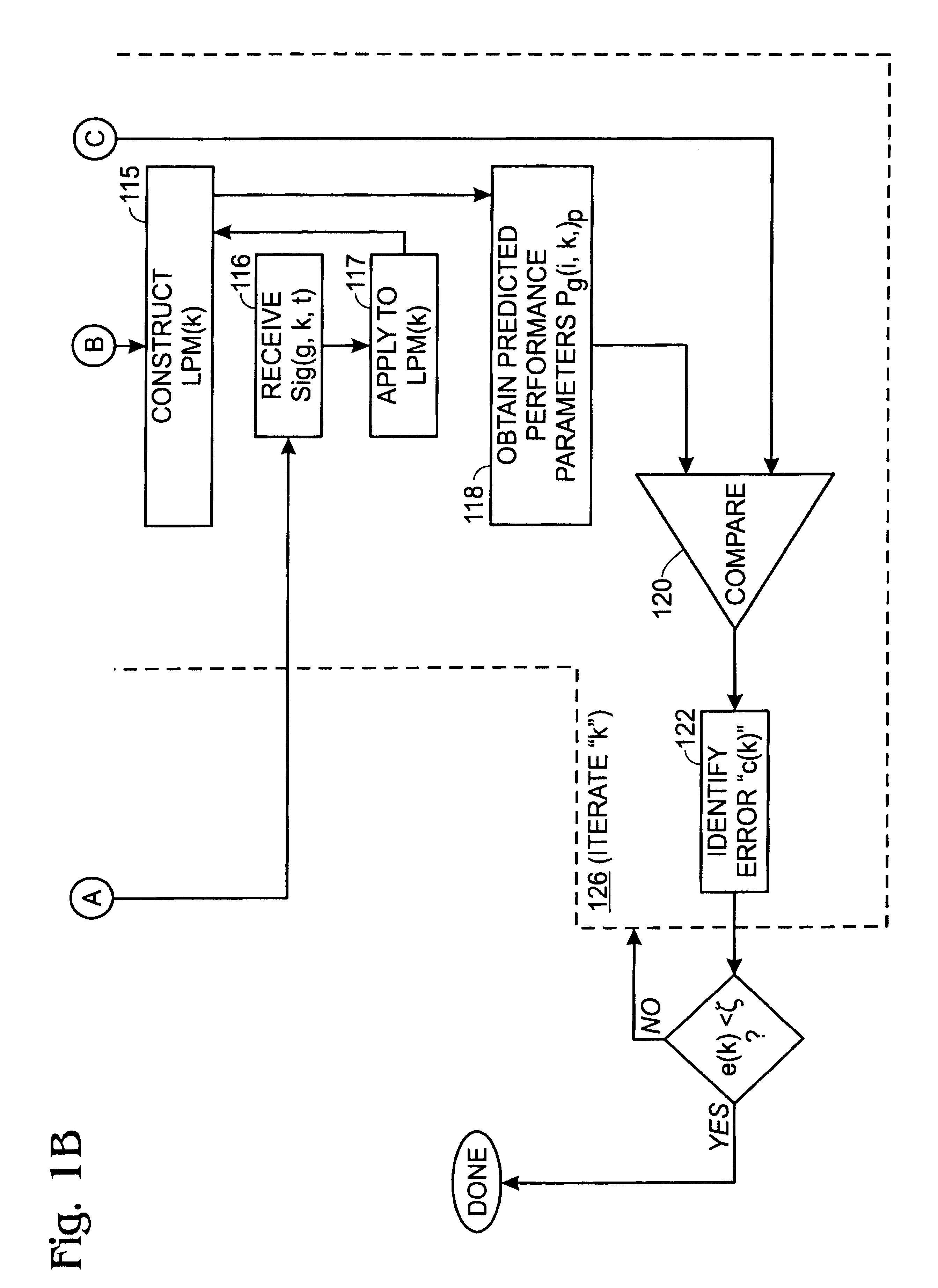
[0025]With reference to FIG. 1, a flow chart of a preferred method for low cost signature testing 100 of electronic circuits is shown. Each of the circuits has a set of performance parameters “P(I), I=1 . . . L, that must fall within a range bounded by a corresponding set of performance specifications. If one or more of the parameters falls outside of the corresponding specification for the parameter, the circuit fails the test; otherwise, the...


PUM


Abstract

A low cost signature test for RF and analog circuits. A model is provided to predict one or more performance parameters characterizing a first electronic circuit produced by a manufacturing process subject to process variation from the output of one or more second electronic circuits produced by the same process in response to a selected test stimulus, and iteratively varying the test stimulus to minimize the error between the predicted performance parameters and corresponding measured values for the performance parameters, for determining an optimized test stimulus. A non-linear model is preferably constructed for relating signature test results employing the optimized test stimulus in manufacturing testing to circuit performance parameters.

Description

[0001]This application is a continuation-in-part of the inventors' prior application Ser. No. 09 / 575,488, filed May 19, 2000, entitled Method for Testing Circuits, now U.S. Pat. No 6,865,500, issued Mar. 8, 2005, and claims the benefit of the provisional application Ser. No. 60 / 197,749, filed Apr. 19, 2000, entitled ATPG for Prediction of Analog Specifications, and Ser. No. 60 / 203,602, filed May 12, 2000, entitled Test Generation for High Frequency and RF Circuits, each incorporated by reference in their entireties herein.BACKGROUND OF THE INVENTION[0002]The present invention relates to a method and apparatus for low cost signature testing for testing analog and RF circuits. More particularly, the invention relates to such a method and apparatus for use in manufacturing testing, and for use in monitoring the manufacturing process.[0003]Analog and RF circuits are characterized by a set of performance parameters that typically vary continuously over a range. These performance paramete...

Claims


Application Information

Patent Timeline
Patent Type & Authority Patents(United States)
IPC IPC(8): G06F11/263G01R31/28
CPCG01R31/2837
Inventor VOORAKARANAM, RAMCHATTERJEE, ABHIJITVARIYAM, PRAMODCHANDRAN N.CHERUBAL, SASIKUMARGOMES, ALFRED V.
Owner GEORGIA TECH RES CORP
Why Eureka
Try Eureka