Chemical mechanical polishing equipment and conditioning thereof

a technology of mechanical polishing equipment and conditioner, which is applied in the field of semiconductor technology of chemical mechanical polishing equipment and the conditioner, can solve the problems of loss of flexibility of the supporting rod, and achieve the effect of improving polishing uniformity and reducing the residual particle ra

Active Publication Date: 2006-03-07
UNITED MICROELECTRONICS CORP
View PDF9 Cites 5 Cited by
  • Summary
  • Abstract
  • Description
  • Claims
  • Application Information

AI Technical Summary

Benefits of technology

[0011]The invention provides a CMP equipment and the conditioner. The conditioning can have substantially full contact with the polishing pad to reduce the residual particles on the polishing pad, so as to improve the polishing uniformity
[0014]For the CMP equipment of the invention, the conditioner is design with multiple conditioning blocks and a clearance exits between the condition blocks. This design allows the conditioner to be flexible and be substantially full contact with polishing pad, so as to reduce the residual rate of the residual particles on the polishing pad and further improve polishing uniformity.

Problems solved by technology

This causes the loss of flexibility for the supporting rod.

Method used


Image

  • Chemical mechanical polishing equipment and conditioning thereof
  • Chemical mechanical polishing equipment and conditioning thereof
  • Chemical mechanical polishing equipment and conditioning thereof

Examples


Embodiment Construction

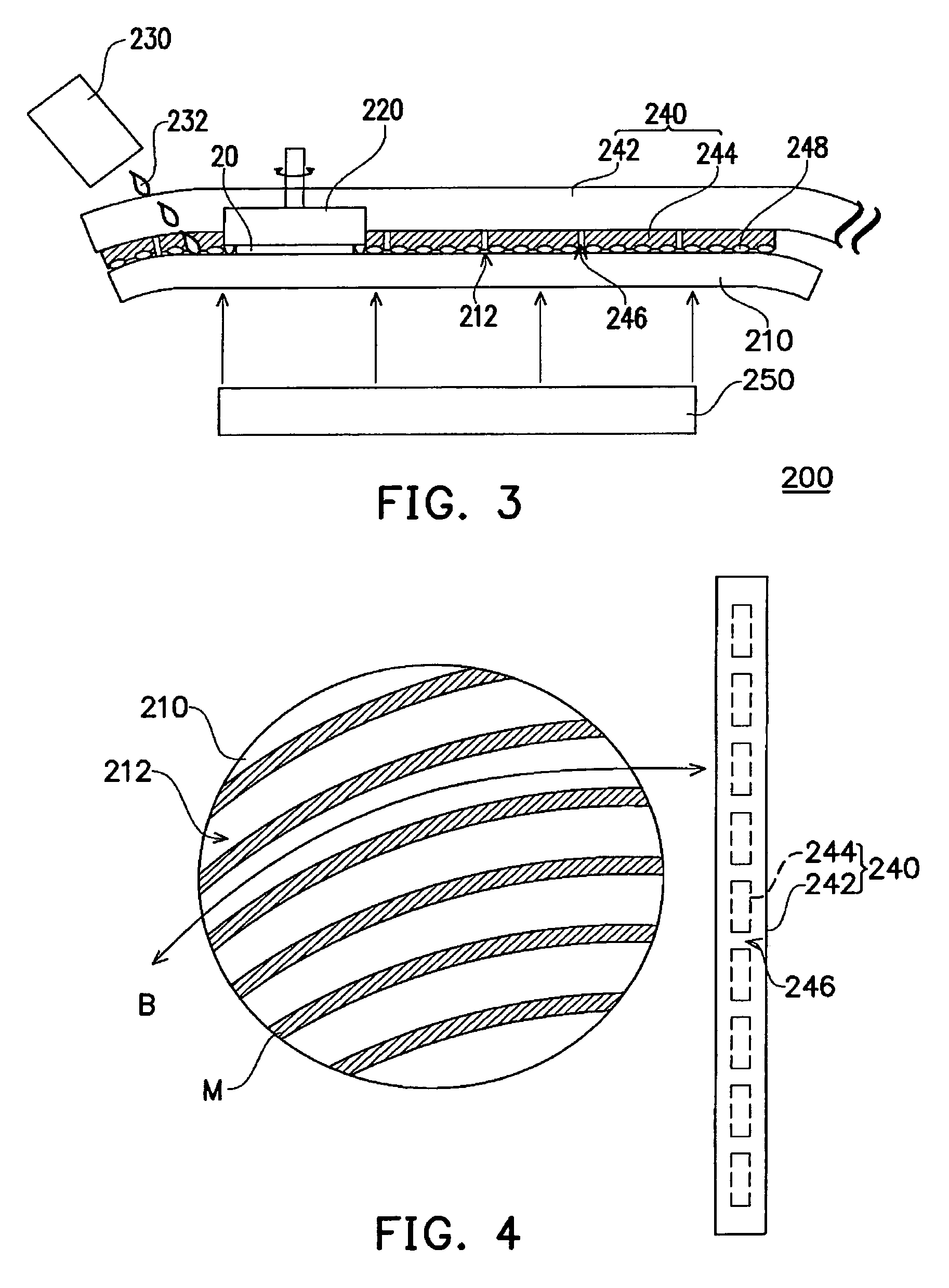
[0023]FIG. 3 is a side view, schematically illustrating a CMP equipment, according to a preferred embodiment of the invention. FIG. 4 is a top view, schematically illustrating a conditioner and polishing pad, according to a preferred embodiment of the invention. In FIGS. 3 and 4, the CMP equipment 200 of the invention includes a polishing pad 210, a holder 220, a slurry supplier 230, a conditioner 240, and a gas supplier 250.

[0024]The polishing pad 210 has a polishing surface 212. The holder 220 is implemented above the polishing pad 210 to hold a wafer 20. This holder 220 carries the wafer 20 to have a relative motion between the surface of the wafer 20 and the polishing surface 212 of the polishing pad 210, so as to polish the surface of the wafer 20. The relative motion between the wafer 20 and the polishing pad 210 includes rotating motion and also the left-right shift motion of the wafer 20.

[0025]The slurry supplier 230 is implemented above the polishing pad 210. The slurry sup...


PUM

PropertyMeasurementUnit
shapesaaaaaaaaaa
hardaaaaaaaaaa
elasticityaaaaaaaaaa

Abstract

A chemical mechanical polishing equipment has a polishing pad, a holder, a slurry supply and a conditioner. The holder is disposed above the polishing pad and carries a wafer for polishing the surface of wafer. The slurry supply is disposed above the polishing pad for supplying slurry onto the polishing surface. The conditioner is disposed near the polishing pad for removing the residual particles over the polishing pad. By disposing a plurality of block on the conditioner, the conditioner can provide with flexibility so that the conditioner can sufficiently contact with the polishing surface for increasing the removal rate of residual particles.

Description

BACKGROUND OF THE INVENTION[0001]1. Field of Invention[0002]The present invention relates to semiconductor technology about the chemical mechanical polishing equipment and the conditioner. More particularly, the present invention relates to the chemical mechanical polishing equipment and the conditioner, which can improve the removing-rate of residual particles on the polishing pad.[0003]2. Description of Related Art[0004]For the planarization technology, the chemical mechanical polishing (CMP) technology has been widely used to have global planarization. In general, during the CMP process, the slurry with suspending abrasive particles and the polishing pad with proper elasticity and hardness are used, so as to achieve the planarization by a relative motion on the wafer surface.[0005]FIG. 1 is a side view, schematically illustrating the conventional CMP equipment. FIG. 2 is a top view, schematically illustrating the conditioner and the polishing pad. In FIG. 1 and FIG. 2, the conven...

Claims


Application Information

Patent Timeline
Patent Type & Authority Patents(United States)
IPC IPC(8): B24B1/00B24B37/04B24B53/12
CPCB24B37/04B24B53/12B24B53/017
Inventor WU, VINSCENTSHIH, HUI-SHENLU, JASON
Owner UNITED MICROELECTRONICS CORP
Why Eureka
Try Eureka