Micro-dialysis probe

a micro-dialysis and probe technology, applied in the field of micro-dialysis probes, can solve the problems of delay in the adjustment of equilibrium, dead space in the shaft in which dialysate is drained, and insufficient flow through such dialysis probes, so as to promote concentration equalisation and increase flow rate

Inactive Publication Date: 2006-03-07
ROCHE DIABETES CARE INC
View PDF14 Cites 12 Cited by
  • Summary
  • Abstract
  • Description
  • Claims
  • Application Information

AI Technical Summary

Benefits of technology

[0008]The present invention relates to a dialysis probe having a supply line and a drainage line for a drip-feed solution and a dialysis section arranged generally therebetween. The dialysis probe is configured such that solution flowing from the supply line to the drainage line experiences an inversion in flow in the area of the dialysis section. Thus, the dialysis probe of the present invention provides stable flow guidance and thus a fast adjustment of the equilibrium. Further, in the dialysis probe of the present invention, flow-impeding dead spaces in the dialysis section and in the supply line and drainage line are substantially avoided.
[0010]A further advantage of the dialysis probe in accordance with the invention is that the supply line and drainage line can each simply run straight in or out of the rear part of the dialysis probe, and flow redirection —in which dead spaces are formed—can be largely avoided.
[0011]In an embodiment of the micro-dialysis probe in accordance with the invention, the first drainage line in the direction of the flow consists of a dialysis hollow fiber penetrating into the supply line behind the inversion, the hollow fiber being fastened in the area of the sealed tip of the probe such that a linear course of flow is achieved after the inversion, while at its other end it is sealed into a second stable section of the drainage line. In this way, the drip-feed solution flows through the whole cross-section of the dialysis hollow fiber in one direction, and the dialysate is introduced into the drainage line linearly, without a change in direction. The flow direction is here inverted, as is necessary to enable the liquid to be supplied and drained from one side, before it enters the dialysis hollow fiber, such that the dialysis itself is not impeded by disturbances in the flow. The previously mentioned stable section is preferably a tube which forms the outer part of the drainage line, i.e. its supporting component. In this way, the part of the tube in the area of the tip of the probe which lies over the hollow fiber, where the dialysis hollow fiber penetrates into the supply line, can form a supporting section to mechanically strengthen this part of the probe.
[0014]An embodiment of the micro-dialysis probe as described above is preferred developed such that the hollow fiber at the supply line end and drainage line end of the probe is sealed into a probe shaft which accommodates and continues the supply line and the drainage line separately. Such a probe shaft ensures a further increase in stability and enables the necessary connections to be provided.
[0017]Although a higher flow rate prevails in the individual supply line due to the smaller cross-section, an efficient exchange of material take also take place here, since the concentration gradient between the drip-feed solution and the surroundings is still at its greatest in this area. After the drip-feed solution has overflowed into the two parallel drainage lines in the immediate vicinity of the tip, the flow rate is halved, which promotes concentration equalisation between the substances passing through the hollow fiber, since more time is available for this purpose.

Problems solved by technology

In the use of viscous drip-feed solutions or at high flow rates in particular, it is evident that the flow through such dialysis probes is not optimal.
Moreover, a dead space arises in the shaft in which the dialysate is drained, due to its construction, at the transfer point into the drainage tube.
Both of these lead to a delay in the adjusting of the equilibrium.
Profiles with such a small diameter and a central bore, however, can only be produced at great cost.

Method used


Image

  • Micro-dialysis probe
  • Micro-dialysis probe
  • Micro-dialysis probe

Examples


first embodiment

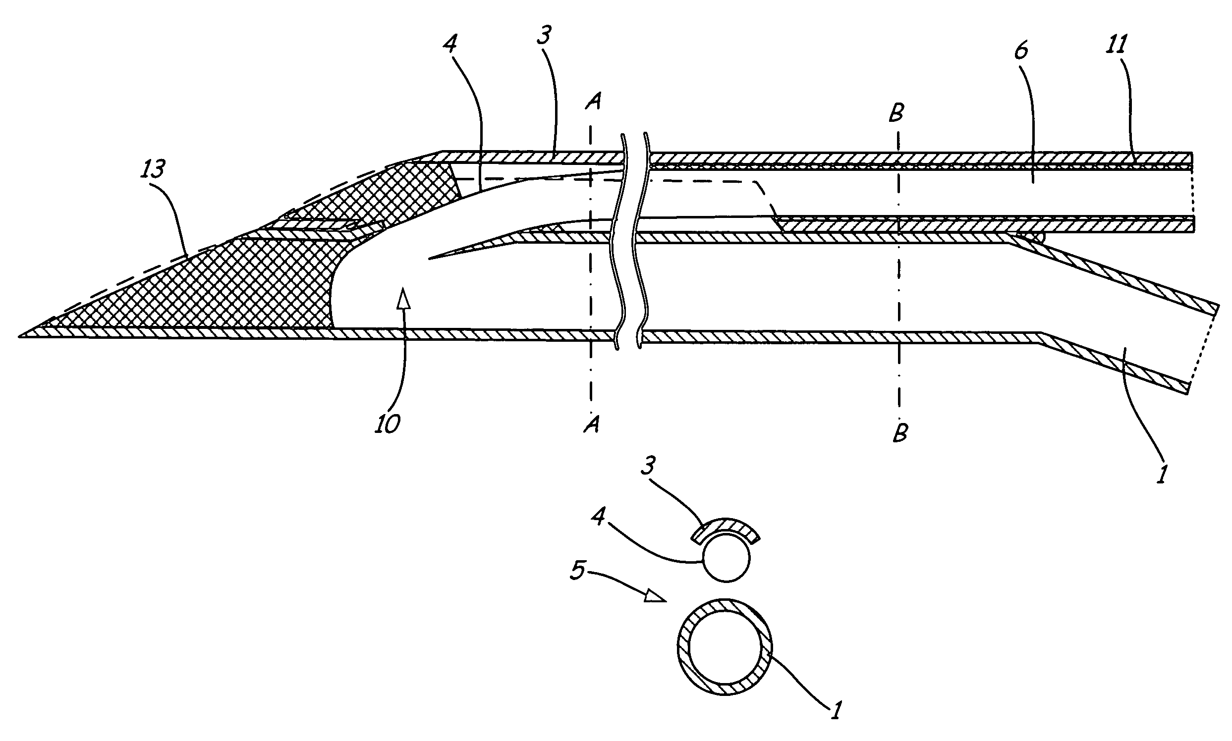
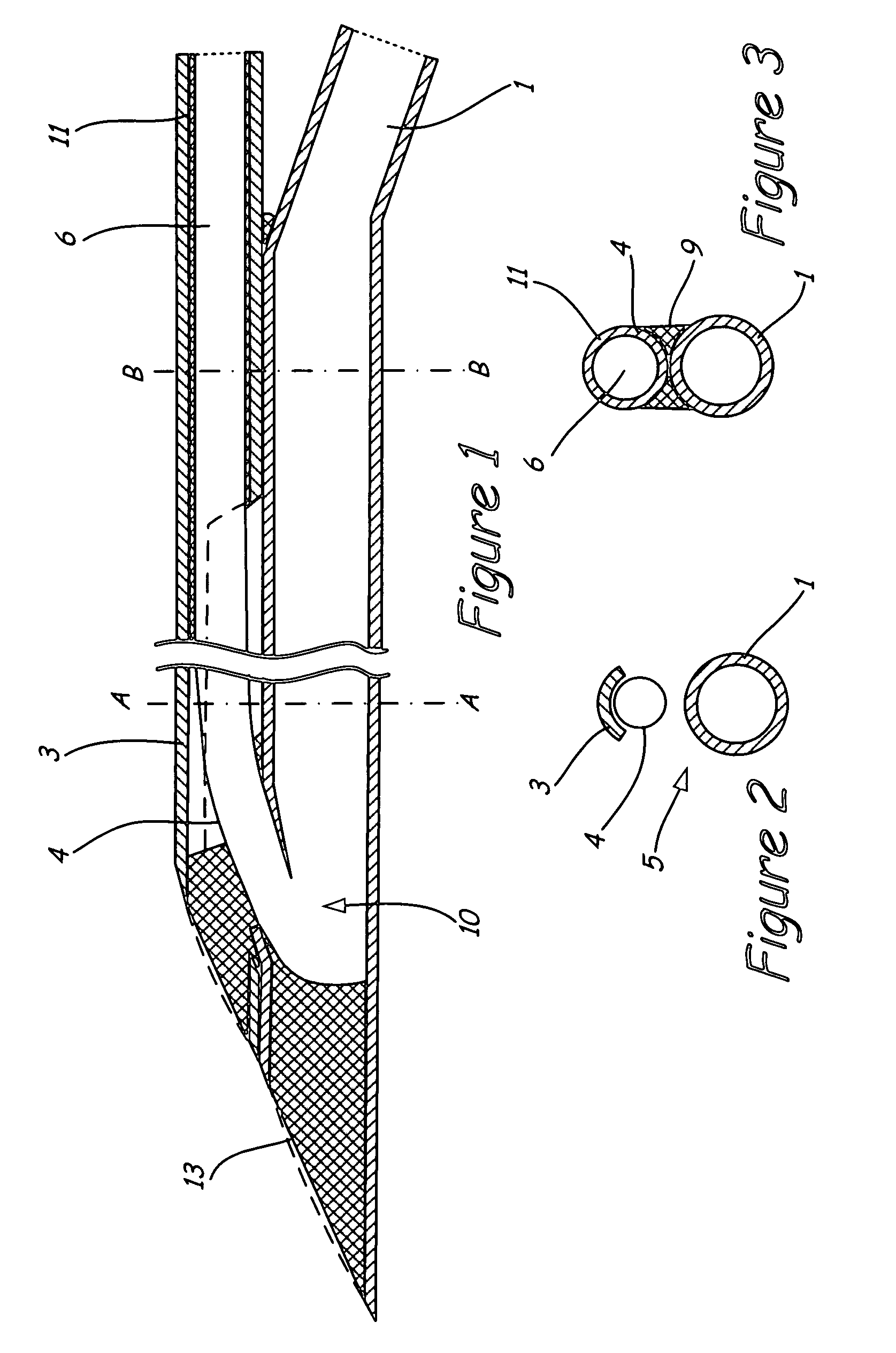
[0028]FIG. 1 illustrates a micro-dialysis probe in accordance with the present invention. The micro-dialysis probe extends longitudinally between a proximal probe opening and a distal probe tip. A supply line 1, or a supply channel, is provided through which the drip-feed solution is introduced into the probe. A drainage line 6, formed by a hollow fiber 4, is provided for draining the drip-feed solution from the probe. A tube 11 may be provided surrounding the drainage line 6 for supporting the drainage line 6. The hollow fiber 4 is may be formed to be replaceable, and correspondingly sealed in, the tube 11. The supply line 1 and drainage line 6 are arranged substantially side-by-side and together form the probe shaft of the micro-dialysis probe. At the distal probe tip, the probe is sealed and pointed with a sealing material 13, to enable it to be introduced into subcutaneous tissue. In the vicinity of the probe tip, a dialysis opening 10 is provided in the supply line 10. The holl...

second embodiment

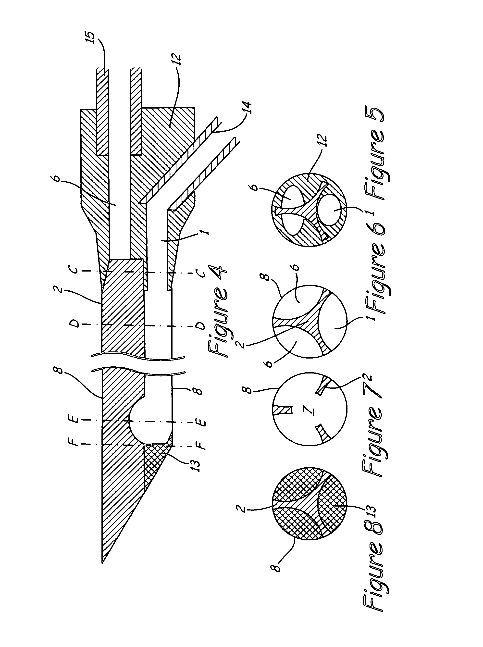
[0033]FIG. 4 illustrates a micro-dialysis probe of the present invention in accordance with a The flow channel for the drip-feed solution consists of a hollow fiber 8 with a supporting profile 2 inserted into it which separates the supply line 1 and the drainage line 6 from one another, the supporting profile 2 having at least one opening 7 in the area of flow inversion. The supply line 1 and drainage line 6, together with the hollow fiber 8, form a part of the outer wall of the probe, but are separated and supported such that the flow is not impeded. The supporting function and flow guidance are assumed by the profile 2. The supporting profile 2 is thus configured such that the volume of the hollow fiber 8 through which the flow may pass consists of a number of elongated hollow spaces. These hollow spaces enable the drip-feed solution to flow into the probe tip and to be re-circulated to the other side, wherein the flow is inverted by the overflow openings.

[0034]As shown in FIG. 4...


PUM


Abstract

A micro-dialysis probe extending longitudinally between a proximal probe opening and a distal probe tip and having a supply line and a drainage line for a drip-feed solution. A tube may be provided for supporting the drainage line. A dialysis section, wherein the flow channel for the drip-feed solution experiences an inversion, is formed generally between the supply line and the drainage line, in the vicinity of the distal probe tip. The supply line and the drainage line are arranged substantially side by side and together form the probe shaft of the micro-dialysis probe.

Description

PRIORITY CLAIM[0001]This application is a continuation of International Application No. PCT / CH00 / 00389, filed on Jul. 18, 2000, which claims priority to German Application No.199 37 099 C2, filed on Aug. 6, 1999, both of which are herein incorporated by reference.BACKGROUND OF THE INVENTION[0002]1. Technical Field[0003]The present invention relates to a micro-dialysis probe having a supply line and a drainage line for a drip-feed solution and a dialysis section positioned generally therebetween. More specifically, the present invention relates to a micro-dialysis probe wherein solution flowing from the supply line to the drainage line experiences an inversion in flow in the area of the dialysis section.[0004]2. Description of the Related Art[0005]Implanted hollow fibers, hollow fiber loops or dialysis probes are used for micro-dialysis in medicine and biological research. Conventional dialysis probes possess a tube-shaped shaft in which dialysate is drained and which comprises a clo...

Claims


Application Information

Patent Timeline
IPC IPC(8): A61M3/00A61B5/00A61M5/14A61M1/16
CPCA61B5/14528A61B5/145
Inventor EHWALD, RUDOLFUWE, BEYERTHOMAS, ANDREAS
Owner ROCHE DIABETES CARE INC
Why Eureka
Try Eureka