
Method and coupling apparatus for facilitating an vascular anastomoses

a coupling apparatus and vascular anastomosis technology, applied in the field of surgery, can solve problems such as irreversible spasm, and achieve the effect of minimizing time and operator dependence inconsistency in performing vascular anastomosis and fast and uniform methods

Inactive Publication Date: 2006-03-07
BARATH PETER
View PDF5 Cites 19 Cited by
  • Summary
  • Abstract
  • Description
  • Claims
  • Application Information

AI Technical Summary

Benefits of technology

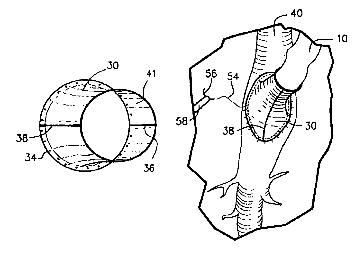
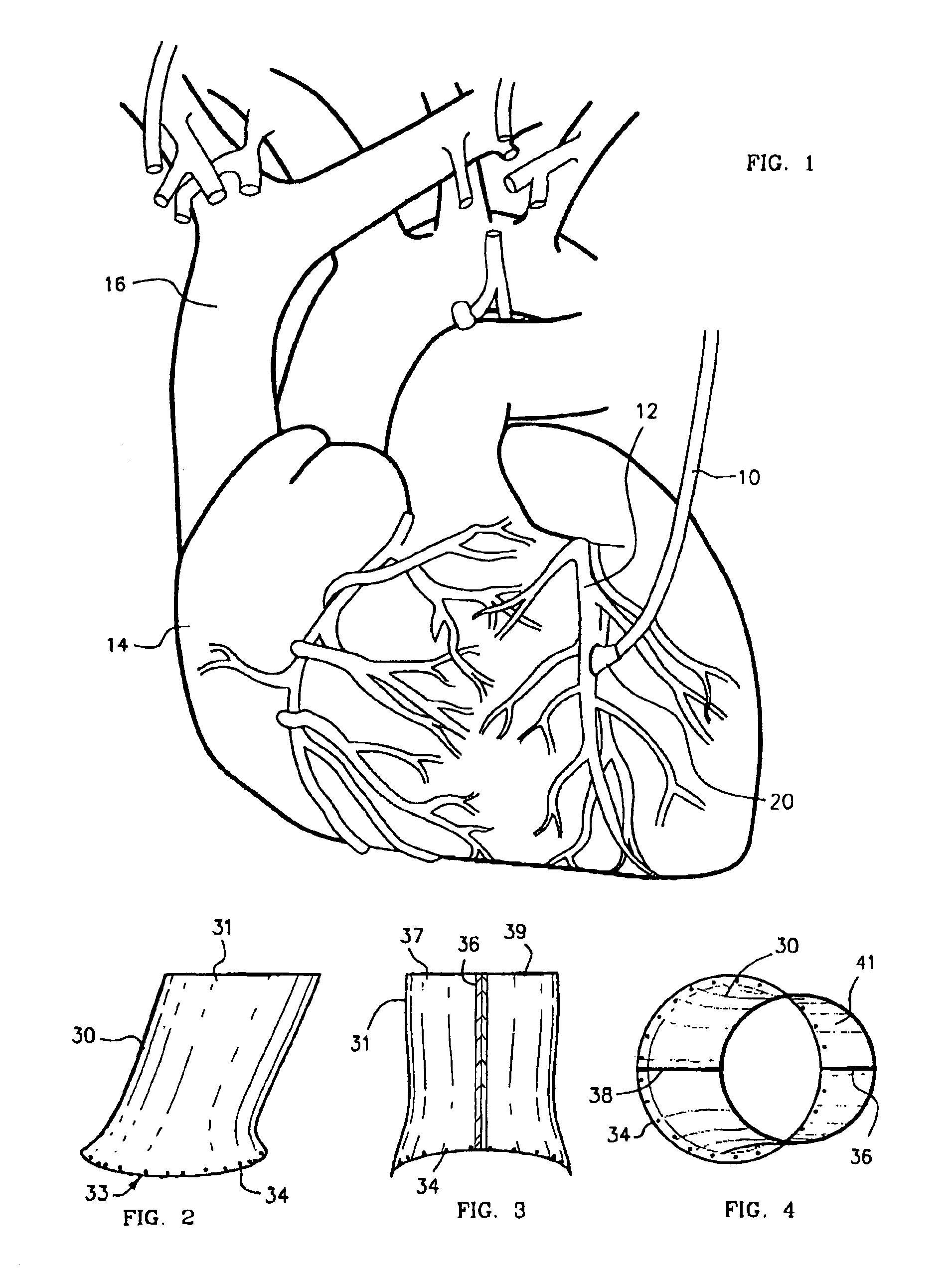
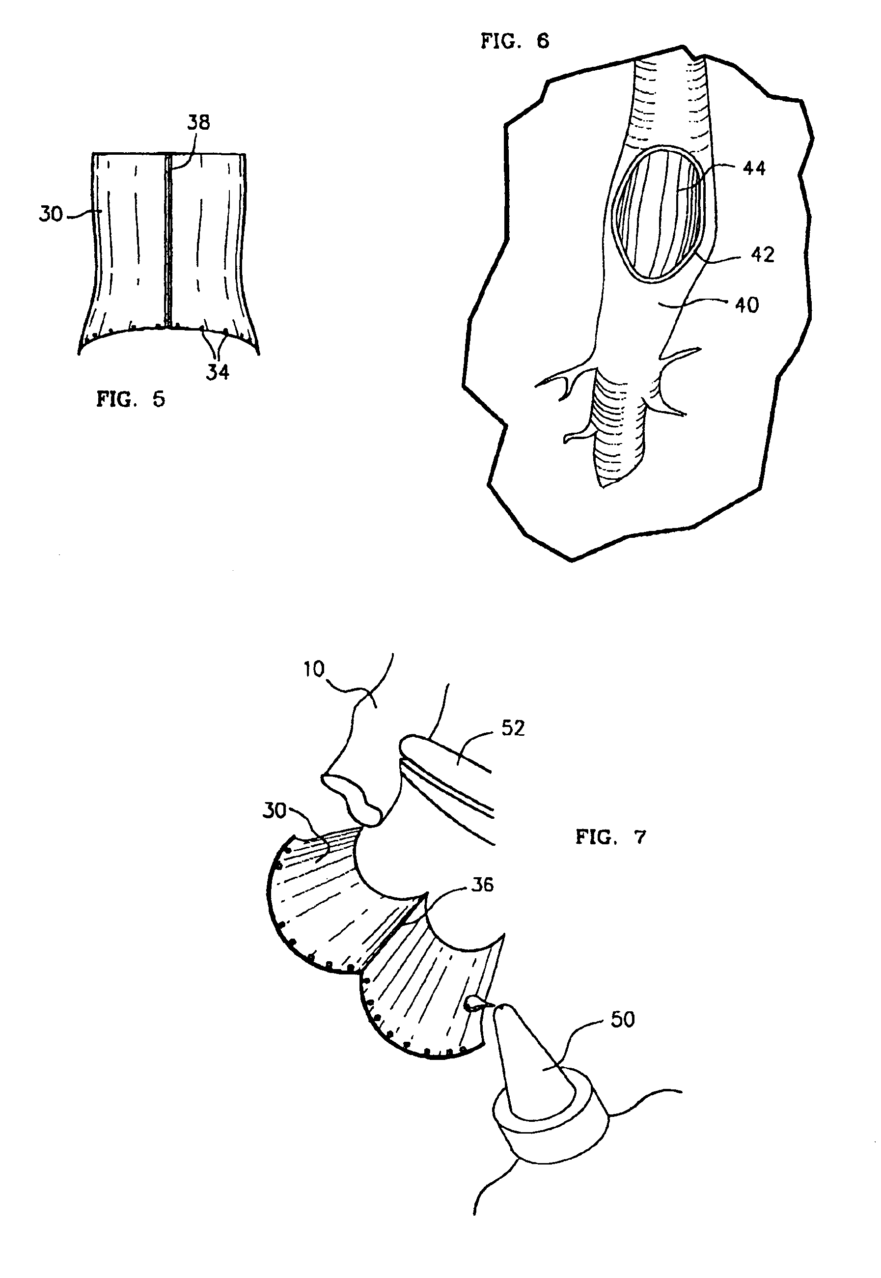
[0007]In general, the advantages of this concept is that a relatively fast and uniform method for facilitating the coupling of various conduits as an anastomoses procedure within various areas of the human body can be achieved. The present invention, which addresses the needs described above, resides in an apparatus and method for coupling vascular apertures to a blood supply vessel in a manner that minimizes the time and operator dependent inconsistency in performing vascular anastomoses. In the coronary setting, this concept is fast and can be applied to both conventional and minimally invasive operative techniques.
[0010]The output end of the coupling apparatus is appropriately prepared for securement means by attachment with staples or sutures and in some cases, by means of additional adhesive or glue application to increase the security of the attachment. Then, the prepared coupling apparatus is positioned in close proximity to the desired anastomosis site on a coronary vessel and finally engaged to the coronary vessel site.

Problems solved by technology

One problem the surgeon faces during any of these above procedures is how to grab the bypassing vessel since the vessel with the interrupted blood flow becomes flabby and hard to handle, does not keep the preferred (i.e. a elongated ) shape to fit exactly the aperture on the target vessel.
Acutely, rough handling of the live conduit artery (i.e. internal mammary artery) might lead irreversible spasm.

Method used


Image

  • Method and coupling apparatus for facilitating an vascular anastomoses
  • Method and coupling apparatus for facilitating an vascular anastomoses
  • Method and coupling apparatus for facilitating an vascular anastomoses

Examples


Embodiment Construction

[0027]The present invention can be used as a means to facilitate the anastomosis procedure and decrease the likelihood of leakage in conventional open-chest, small incision bypass surgeries on and off cardiopulmonary bypass. These procedures are well known by those skilled in the art and recitation of these procedures is not reproduced here.

[0028]Alternately, in closed chest thoracoscopic methods, the present invention can employed as describe herein. In preparation for the surgical procedure of the present invention, the patient is placed on the operating table in a supine position, and general anaesthesia administered. The patient is selectively intubated using conventional methods with a double-lumen endotracheal tube, thereby permitting the left lung to be deflated. The patient is then placed in a lateral decubitus position on his right side. Next, based upon the pathology and anatomy of the patient, the surgeon identifies a suitable position for insertion of a Beress insufflati...


PUM


Abstract

The present invention, which addresses the needs described above, resides in an apparatus and method for coupling vascular apertures to a blood supply vessel in a manner that minimizes the time and operator dependent inconsistency in performing vascular anastomoses. In the coronary setting, this concept is fast and can be applied to both conventional and minimally invasive operative techniques. In the preferred embodiment, the present invention relates to an apparatus and method for facilitating end-to-side vascular anastomoses procedure, whereby the present invention acts as a coupling apparatus between a first, blood supplying hollow organ, e.g. the LIMA, radial artery, or a saphenous vein and the side wall of second hollow organ, typically one of the major coronary arteries, such as the left coronary artery (LCA), right coronary artery (RCA) or the circumflex (CX).

Description

PRIOR APPLICATIONS[0001]This invention was disclosed in a Disclosure Document numbered 448542 entitled “Anastomosis Coupling Apparatus” and submitted to the Patent and Trademark Office on Dec. 8, 1998.FIELD OF THE INVENTION[0002]This invention relates generally to the field of surgery and, more particularly, to a method and device for performing conventional or minimally invasive bypass surgery. More specifically, the present invention relates to a method and a device to perform end-to-side vasculature anastomoses with either conventional or minimally invasive methods coupling a conduit vein or artery with a normal segment of a coronary or other vessel distal to the diseased, narrowed segment.BACKGROUND OF THE INVENTION[0003]In the context of coronary vessel disease, the flow of oxygenated blood to the myocardium of the heart is inhibited by a stenosis or obstruction on one or more of the coronary arteries, Flow can be restored by providing a coronary artery bypass graft (CABG). In ...

Claims


Application Information

Patent Timeline
Patent Type & Authority Patents(United States)
IPC IPC(8): A61B17/04A61B17/00A61B17/11A61B17/115
CPCA61B17/11A61B17/00491A61B17/0469A61B2017/1135A61B17/115A61B2017/1107
Inventor BARATH, PETER
Owner BARATH PETER
Learn More