Method for controlling injection of electric injection molding machine

a technology of injection molding machine and control method, which is applied in the direction of auxillary shaping apparatus, manufacturing tools, ceramic shaping apparatus, etc., can solve the problems of poor controllability, difficult maintenance of stable molding precision, and inability to obtain similar quality. , to achieve the effect of good quality

Inactive Publication Date: 2006-03-07
TOSHIBA MASCH CO LTD
View PDF7 Cites 3 Cited by
  • Summary
  • Abstract
  • Description
  • Claims
  • Application Information

AI Technical Summary

Benefits of technology

[0010]An object of the present invention is to provide an electric injection molding machine capable of molding an article having a good quality when transplanting molding conditions in a hydraulic injection molding machine to an electric injection molding machine as they are.

Problems solved by technology

On the other hand, in a hydraulic injection molding machine for injecting a molding material by hydraulics, changes in the temperature of the hydraulic working oil exerts an influence upon the working characteristics of the machine, so the maintenance of a stable molding precision is difficult.
Also, the viscoelastic property (compressibility) of the working oil and the characteristics of the hydraulic equipment are not negligible magnitudes, so there are the problems in that nonlinearity is apt to occur between the control references and actual injection speed and injection pressure, so the controllability is poor.
In order to mold similar molded articles, there are various problems in shifting from hydraulic injection molding machines to electric injection molding machines.
For example, even if setting molding conditions giving a good molding quality set for a hydraulic injection molding machine (injection speed pattern) as they are for an electric injection molding machine, a similar quality is not always obtained.
For this reason, it was difficult to transplant molding conditions (injection speed pattern) set for a hydraulic injection molding machine to an electric injection molding machine as they are and it was difficult to effectively utilize the molding conditions accumulated in a hydraulic injection molding machine for an electric injection molding machine.
Also, when using the molding conditions set for a hydraulic injection molding machine in an electric injection molding machine and for example injection molding using a mold having a plurality of cavities, there was also the problem that the fluctuations in weight among several molded articles became large.
Therefore, most of the molding material heads toward the route through which the material most easily flows in the mold, so the amounts of material filled in the cavities become nonuniform.
It is possible to set molding conditions for reducing the variation of weight among a plurality of molded articles in an electric injection molding machine, but it is very difficult to determine such molding conditions.
Therefore, much time and labor are required for setting the molding conditions.

Method used


Image

  • Method for controlling injection of electric injection molding machine
  • Method for controlling injection of electric injection molding machine
  • Method for controlling injection of electric injection molding machine

Examples


Embodiment Construction

[0032]Below, an explanation will be made of embodiments of the present invention by referring to the drawings.

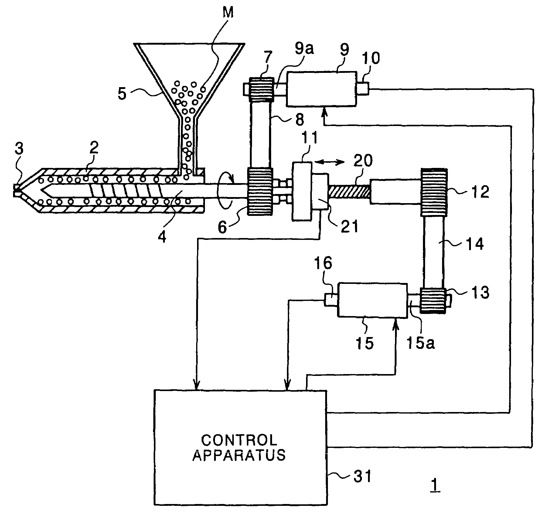
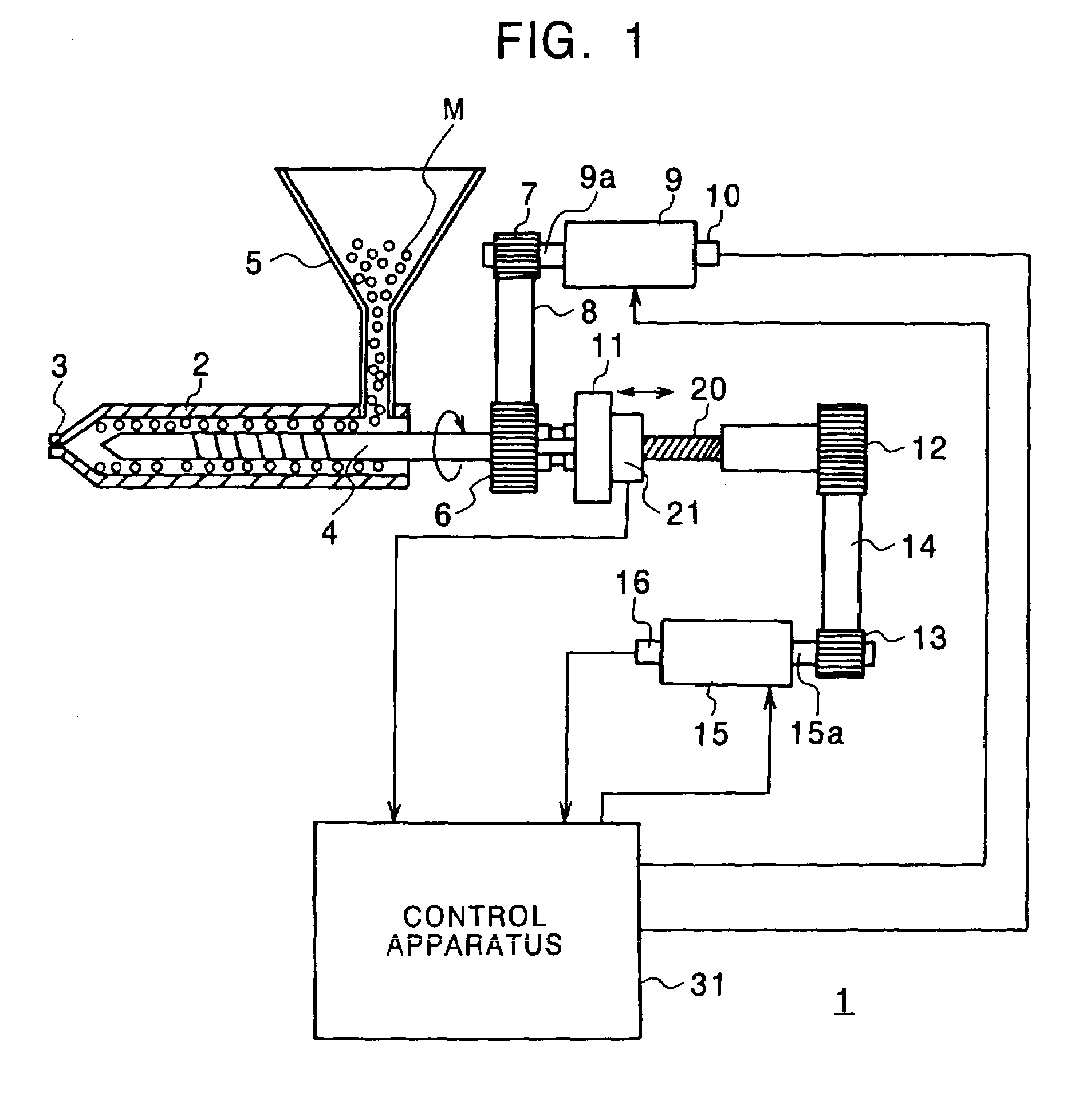
[0033]FIG. 1 is a view of the configuration of an example of an electric injection mechanism of an electric injection molding machine to which the present invention is applied.

[0034]In FIG. 1, an electric injection mechanism 1 is provided with an injection cylinder 2 equipped with an injection nozzle 3 at its front end, an injection screw 4 moveably built in this injection cylinder 2, a hopper 5 for feeding the molding material into the injection nozzle 3, a plasticizing motor 9 for rotating the injection screw 4, and an injection motor 15 for directly moving the injection screw 4.

[0035]The injection cylinder 2 is provided with a not illustrated heating means for heating and melting a molding material M made of for example a rubber material or resin material. The molding material M is fed from the hopper 5.

[0036]The injection nozzle 3 provided at the front end of the injecti...


PUM

PropertyMeasurementUnit
drive forceaaaaaaaaaa
pressureaaaaaaaaaa
injection speedaaaaaaaaaa

Abstract

An electric injection molding machine capable of maintaining a quality of molded articles and capable of suppressing a variation of weight of articles molded by a mold having a plurality of cavities when transferring molding conditions in a hydraulic injection molding machine as they are to the electric injection molding machine. This electric injection molding machine has an electric injection mechanism for injecting a molding material into a mold by a drive force of an electric motor, an injection control unit and a servo driver for controlling the injection motor so as to follow the injection speed reference, and an reference compensation unit for compensating the injection speed reference based on the characteristics of the hydraulic drive system so that fluctuation characteristics of the injection speed with respect to the injection pressure when controlling the electric injection mechanism approximate the fluctuation characteristics of the injection speed with respect to the injection pressure in the hydraulic injection mechanism performing the injection of the molding material to the mold by the hydraulic drive system.

Description

CROSS-REFERENCE TO RELATED APPLICATIONS[0001]This is a Divisional Application of U.S. application Ser. No. 09 / 908,491, filed Jul. 19, 2001 now U.S. Pat. No. 6,669,459, which claims priority from the prior Japanese Patent Application No. 2000-225952, filed Jul. 26, 2000, the entire contents both of which are incorporated herein by reference.TECHNICAL FIELD OF THE INVENTION[0002]The present invention relates to an electric injection molding machine and a method for controlling injection of the same.DESCRIPTION OF THE RELATED ART[0003]Injection control of an electric injection molding machine for injecting a molding material by the drive force of a servo motor is characterized in that the injection speed and the injection pressure can be controlled with a good response since the servo motor follows control references with a good precision and therefore maintenance of a stable molding precision is possible.[0004]On the other hand, in a hydraulic injection molding machine for injecting a...

Claims


Application Information

Patent Timeline
Patent Type & Authority Patents(United States)
IPC IPC(8): B29C45/77B29C45/50
CPCB29C45/77B29C2945/76006B29C2945/76083B29C2945/76498B29C2945/76936B29C2945/76665B29C2945/76785B29C2945/76859B29C2945/76605
Inventor MATSUBAYASHI, HARUYUKIIIMURA, YUKIOYAMAZAKI, TAKASHIKANDA, AKIRAYAMASHITA, TAKAMITSUYAMAGUCHI, YUTAKASUZUKI, MASAMITSU
Owner TOSHIBA MASCH CO LTD
Why Eureka
Try Eureka