Pulse signal generator and display device

a technology of pulse signal and display device, which is applied in the direction of generating/distributing signals, pulse techniques, instruments, etc., can solve the problems of high communication speed required between the controller and the led driver, and becomes very difficult to transmit the high-frequency signal shown in equation 1, and the cost of high-frequency signal transmission is increased. , to achieve the effect of reducing the amount of information of pulse assignment signal, simplifying wiring configuration, and reducing the amount of information

Active Publication Date: 2006-03-07
TEXAS INSTR INC
View PDF1 Cites 10 Cited by
  • Summary
  • Abstract
  • Description
  • Claims
  • Application Information

AI Technical Summary

Benefits of technology

[0047]Because the input of the pulse string is made valid / invalid corresponding to the enable signal, when pulse signals are generated by plural pulse signal generators, it is possible to use a common pulse string given to all of the pulse signal generators so as to simplify the wiring, and, at the same time, it is possible to input the desired pulse string to each pulse signal generator corresponding to the enable signal. For example, by controlling the pulse interval of the pulse string input to each pulse signal generator corresponding to the desired pulse width of the pulse signal to be generated, it is possible to reduce the amount of information of the pulse assignment signal.
[0074]In this way, it is possible to transmit the pulse assignment signal between plural pulse signal generators connected in cascade through second input terminals and second output terminals. Compared to the case when the enable signals are sent through independent wirings to the respective pulse signal generators with this scheme, the wiring can be simplified.

Problems solved by technology

Consequently, a very high communication speed is required between the controller and the LED driver, which is undesirable.
For example, with a square display panel measuring several meters per side, it becomes very difficult to transmit the high-frequency signal shown in Equation 1.
However, since the number of controllers is quadrupled, the cost increases, which is undesirable.
However, the circuit constitution of the PWM grayscale control type LED driver is more complicated than that of the single-grayscale type LED driver.
As a result, the cost increases, which is undesirable.

Method used


Image

  • Pulse signal generator and display device
  • Pulse signal generator and display device
  • Pulse signal generator and display device

Examples


embodiment 1

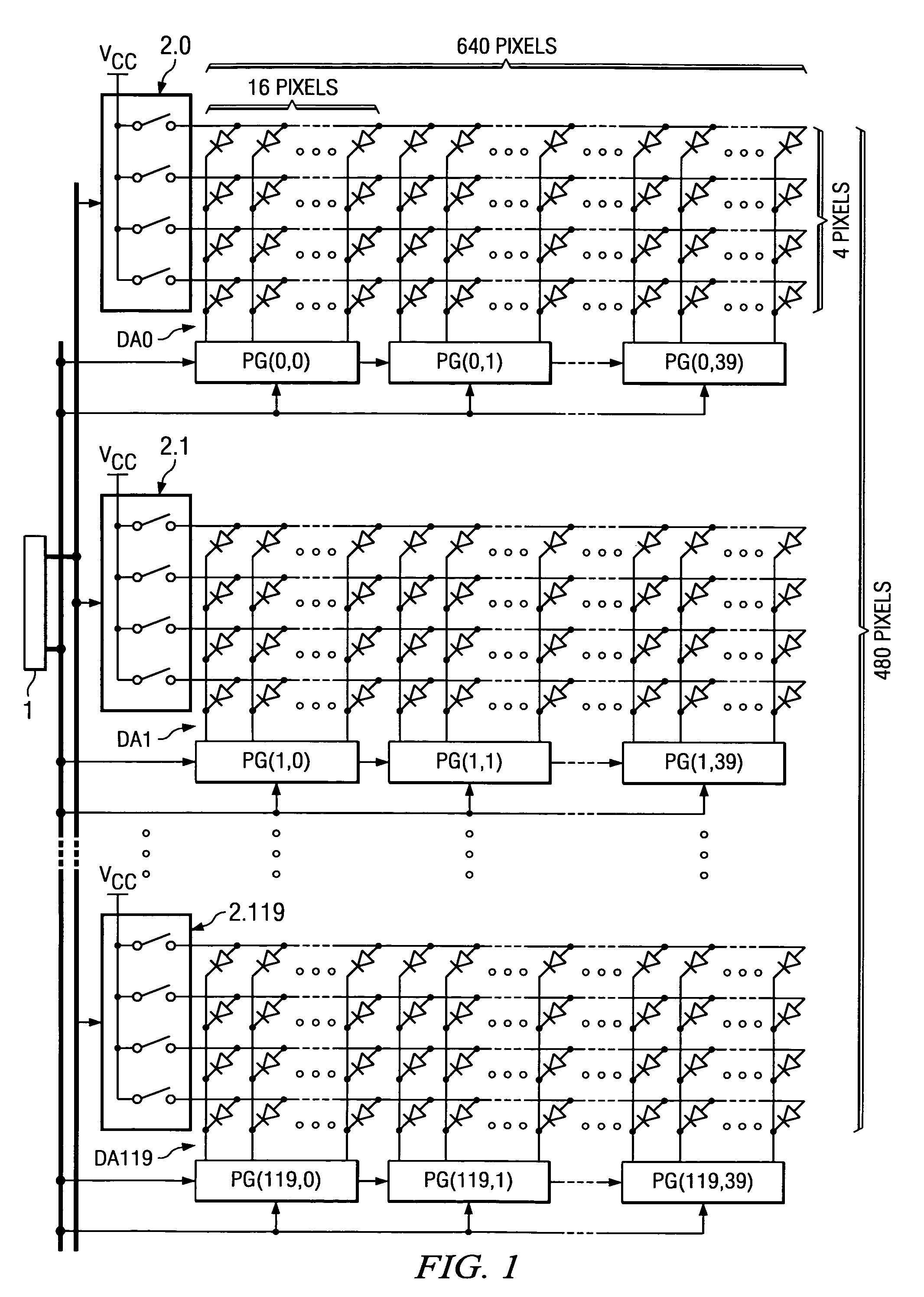
[0095]FIG. 1 is a block diagram illustrating an example of the constitution of the display device in Embodiment 1 of the present invention.

[0096]The display device shown in FIG. 1 includes control unit 1, horizontal line selection units 2_0–2_119, LED arrays DA0–DA119, and pulse signal generating units PG(0,0)–PG(119,39).

[0097]Control unit 1 is an embodiment of the control means of the present invention.

[0098]LED arrays DA0–DA119 are an embodiment of the display elements of the present invention.

[0099]Pulse signal generating units PG(0,0)–(119,39) are an embodiment of the pulse signal generators of the present invention.

[0100]Control unit 1 generates the control signals to be explained later for pulse signal generating units PG(0,0)–PG(119,39) on the basis of the information of the display image. With said control signals, the pulse width of the pulse signals for driving LEDs of LED arrays DA0–DA119 is controlled. Also, horizontal line selection units 2_0–2_119 generate control sign...

embodiment 2

[0162]Embodiment 2 of the present invention will be explained below.

[0163]In the display device in Embodiment 2, for example, control unit 1 and pulse signal generating units PG(i,j) in the display device shown in FIG. 1 are replaced by control unit 1A and pulse signal generating units PGA(i,j), to be explained below.

[0164]FIG. 6 is a block diagram illustrating the constitution of a horizontal line extracted from the display device in Embodiment 2 of the present invention.

[0165]Clock signal CLK output from control unit 1A, latch signal S_LAT, and pulse string PS are input to pulse signal generating unit PGA(i,j).

[0166]Also, pulse signal generating unit PGA(i,j) takes enable signal DE and pulse assignment signal DP output from previous-stage pulse signal generating unit PGA(i,j−1) as input, and holds input enable signal DE and pulse assignment signal DP synchronously with clock signal CLK, while outputting it to next-stage pulse signal generating unit PGA(i,j+1).

[0167]That is, pulse ...

embodiment 3

[0217]Embodiment 3 of the present invention will be explained below.

[0218]In Embodiment 3, for example, operation of control unit 1A of the display device shown in FIG. 6 is changed in accordance with the explanation below. Also, the remaining features of the constitution and operation may be the same as those of the display device shown in FIG. 6.

[0219]FIG. 10 is a timing diagram illustrating an example of the timing relationship of the various signals of the display device of Embodiment 3 of the present invention shown in FIG. 6.

[0220]FIG. 10(A) is a diagram illustrating the signals output from control unit 1A.

[0221]FIG. 10(B) is a diagram illustrating the pulse assignment signal held in signal holding unit 4 of pulse signal generator PGA(i,j).

[0222]FIG. 10(C) is a diagram illustrating clock signal CLK output from control unit 1A.

[0223]FIG. 10(D) is a diagram illustrating latch signal S_LAT output from control unit 1A.

[0224]FIGS. 10(E)–(H) illustrate enable signals DE0–DE39 held i...


PUM


Abstract

The objective of this invention is to provide a pulse signal generator with a simple constitution that can reduce the number of signals required for setting the pulse width, as well as a display device using said pulse signal generator. Pulse assignment signal DP0 input to the initial stage of pulse signal generating units PG(i,0)–PG(i,39) connected in cascade is sequentially transferred towards the last stage of the cascade connection. After transfer of the pulse assignment signal to the pulse signal generating unit in each stage, the count value of said pulse signal generating unit is initialized. Then, the pulses of pulse strings PS0–PS39 in the various pulse signal generating units are counted. The count value of the pulse string is compared to the pulse assignment signal in the comparison unit of each pulse signal generating unit, and, in accordance with the comparison result, the level of the drive pulse signal of the LED is inverted. The pulse intervals (pulse timing) of pulse strings PS0–PS39 are controlled individually by control unit 1 so that the drive pulse signal output from the pulse signal generating unit has the desired pulse width.

Description

FIELD OF THE INVENTION[0001]The present invention pertains to a pulse signal generator, such as a pulse signal generator that generates pulse signals for driving LEDs or other display elements in a PWM (pulse width modulation) system, and a display device having said pulse signal generator.BACKGROUND OF THE INVENTION[0002]In recent years, large LED display devices have enjoyed great popularity in concert halls, stadiums, public squares, and other locations.[0003]LED display devices usually have hundreds of thousands of LEDs to display the various pixels making up the various images, LED drive ICs (hereinafter referred to as LED drivers) for driving said LEDs, and controllers for controlling the LED drivers corresponding to the gradation information of the pixels. Said LEDs are driven with pulse currents supplied from said LED driver. For example, they are driven to be on / off for about 200 cycles / sec. Because the on / off period is very short, the luminance of the LED appear continuous...

Claims


Application Information

Patent Timeline
Patent Type & Authority Patents(United States)
IPC IPC(8): G06F1/04G06M7/00G09G3/36G09G3/20G09G3/32H03K7/08
CPCG09G3/2014G09G3/2085G09G3/2088G09G3/32H03K7/08G09G3/3216G09G2300/06G09G2310/0221G09G2310/027G09G2310/0275G09G3/3283
Inventor NOGAWA, MASASHITATEISHI, TETSUONAKAMURA, HIROKO
Owner TEXAS INSTR INC
Why Eureka
Try Eureka