Device and method for driving plasma display panel

a plasma display panel and display panel technology, applied in the direction of instruments, static indicating devices, etc., can solve the problems of large inrush current generation, inability to recover 100% energy, and require resistor current restriction, so as to reduce the stress of elements and reduce the rising and falling time of sustain-discharging pulses

Inactive Publication Date: 2006-03-07
SAMSUNG SDI CO LTD
View PDF10 Cites 8 Cited by
  • Summary
  • Abstract
  • Description
  • Claims
  • Application Information

AI Technical Summary

Benefits of technology

[0012]In accordance with the present invention a PDP driving circuit for reducing stress of elements and also decreasing rising time and falling time of sustain-discharging pulses

Problems solved by technology

Since the DC PDPs have electrodes exposed in the discharge space, they allow the current to flow in the discharge space while the voltage is supplied, and therefore they problematically require resistors for current restriction.
In the conventional power recovery circuits, however, it is required to always charge the power recovery capacitor by a half of the sustain-discharging voltage immediately after the light has emitted, and when this is not done, a very large inrush current may be generated when a s

Method used


Image

  • Device and method for driving plasma display panel
  • Device and method for driving plasma display panel
  • Device and method for driving plasma display panel

Examples


Embodiment Construction

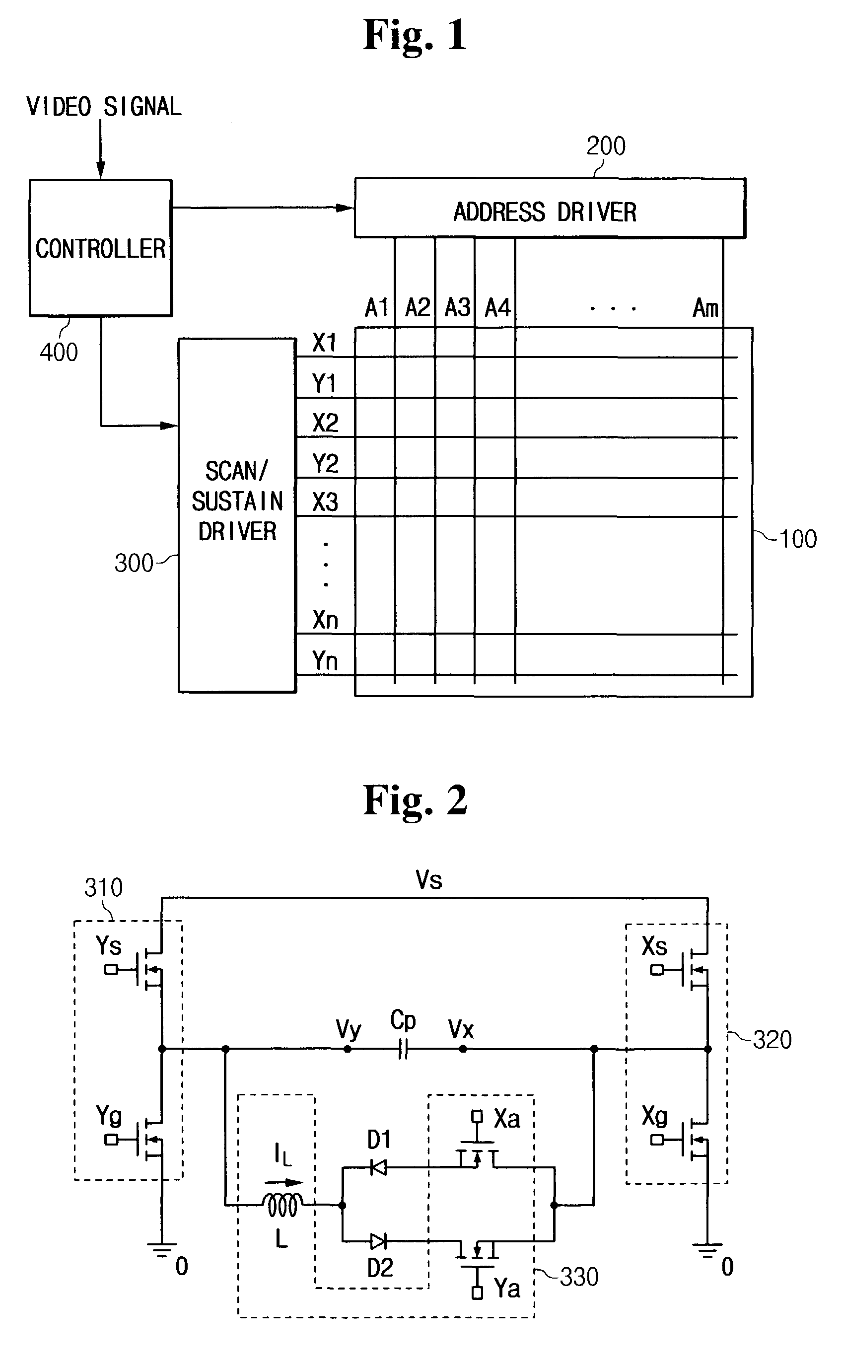
[0024]FIG. 1 shows a PDP according to an embodiment of the present invention which includes plasma panel 100, address driver 200, scan and sustain driver 300, and controller 400.

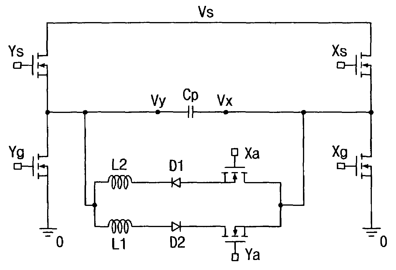
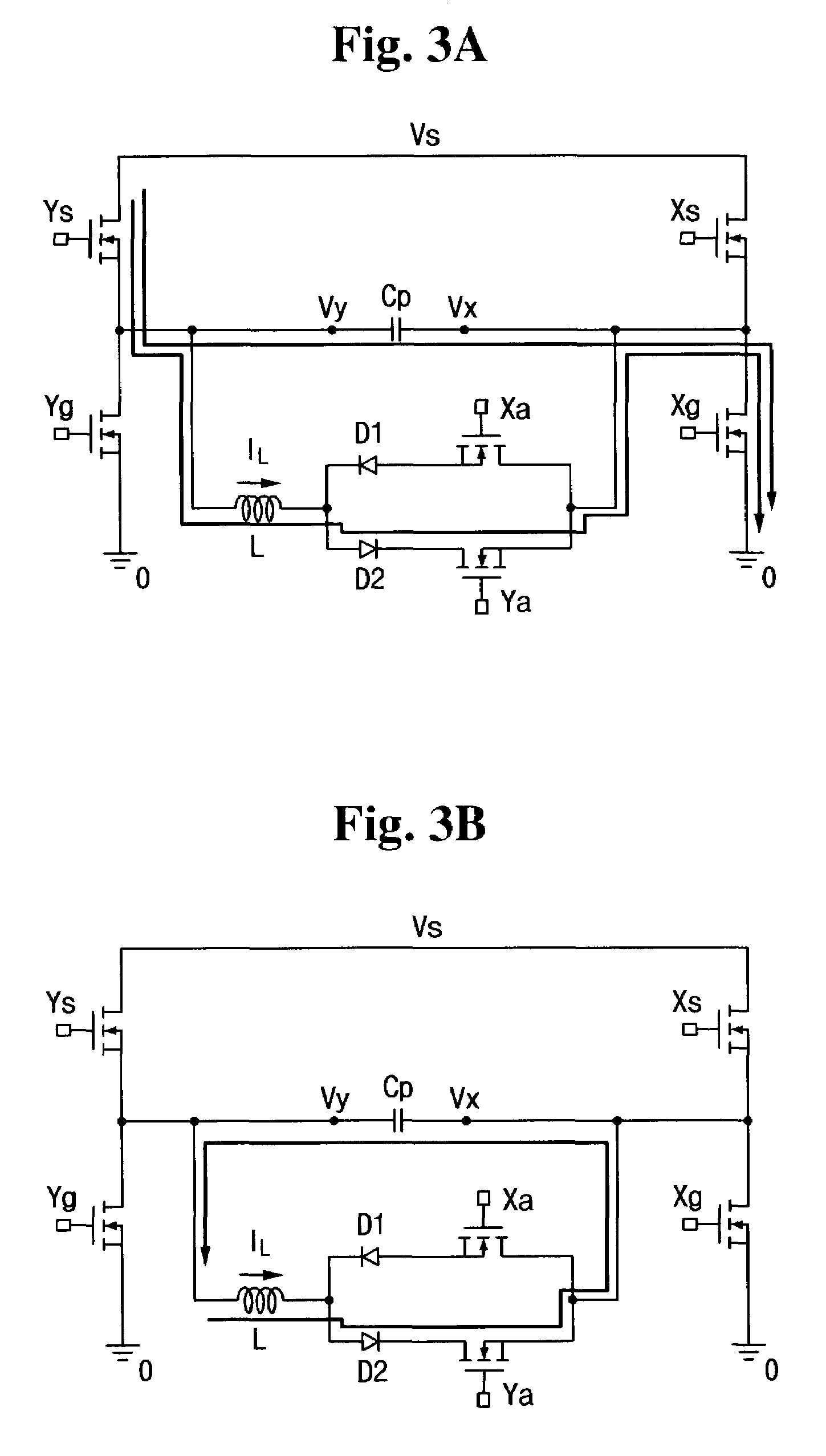
[0025]Plasma panel 100 includes a plurality of address electrodes A1 through Am arranged in the column direction, and a plurality of scan electrodes Y1 through Yn and sustain electrodes X1 through Xn alternately arranged in the row direction. Address driver 200 receives an address driving control signal from controller 400, and applies a display data signal for selecting a discharge cell to be displayed to respective address electrodes A1 through Am. Scan and sustain driver 300 includes a sustain-discharge circuit for receiving a sustain driving control signal from controller 400, and alternately applies sustain-discharging pulses to scan electrodes Y1 through Yn and sustain electrodes X1 through Xn to sustain the selected discharge cells. Controller 400 externally receives a video signal, generates an addre...


PUM


Abstract

In a PDP driver, first and second signal lines for a voltage of Vs and third and fourth signal lines for a voltage of 0V are formed. While maintaining Y and X electrodes of the panel capacitor at Vs and 0V, a first current path is formed from the first signal line to the fourth signal line through an inductor to supply a first-directional current to the inductor. A second current path is formed from the Y electrode to the X electrode through the inductor to change the Y and X electrode voltages using the resonance. When the electrode voltages become 0V and Vs, a third current path is formed from the third signal line to the second signal line through the inductor to reduce the first-directional current.

Description

CROSS REFERENCE TO RELATED APPLICATION[0001]This application claims priority to and the benefit of Korea Patent Application No. 2002-43254 filed on Jul. 23, 2002 in the Korean Intellectual Property Office, the content of which is incorporated herein by reference.BACKGROUND OF THE INVENTION[0002](a) Field of the Invention[0003]The present invention relates to a device and method for plasma display panels (PDPs). More specifically, the present invention relates to a PDP sustain-discharge circuit.[0004](b) Description of the Related Art[0005]Recently, liquid crystal displays (LCDs), field emission displays (FEDs), and PDPs have been actively developed. From among the flat panel devices the PDPs have better luminance and light emission efficiency compared to the other types of flat panel devices, and also have wider view angles. Therefore, PDPs have come into the spotlight as substitutes for the conventional cathode ray tubes (CRTs) in large displays of greater than 40 inches.[0006]The ...

Claims


Application Information

Patent Timeline
IPC IPC(8): G09G3/28G09G3/10G09G3/20G09G3/00G09G3/288G09G3/291G09G3/294G09G3/296
CPCG09G3/2965G09G2330/025G09G3/296
Inventor LEE, JUN-YOUNGKIM, JIN-SUNGCHOI, HAK-KIHAN, CHAN-YOUNG
Owner SAMSUNG SDI CO LTD
Why Eureka
Try Eureka