

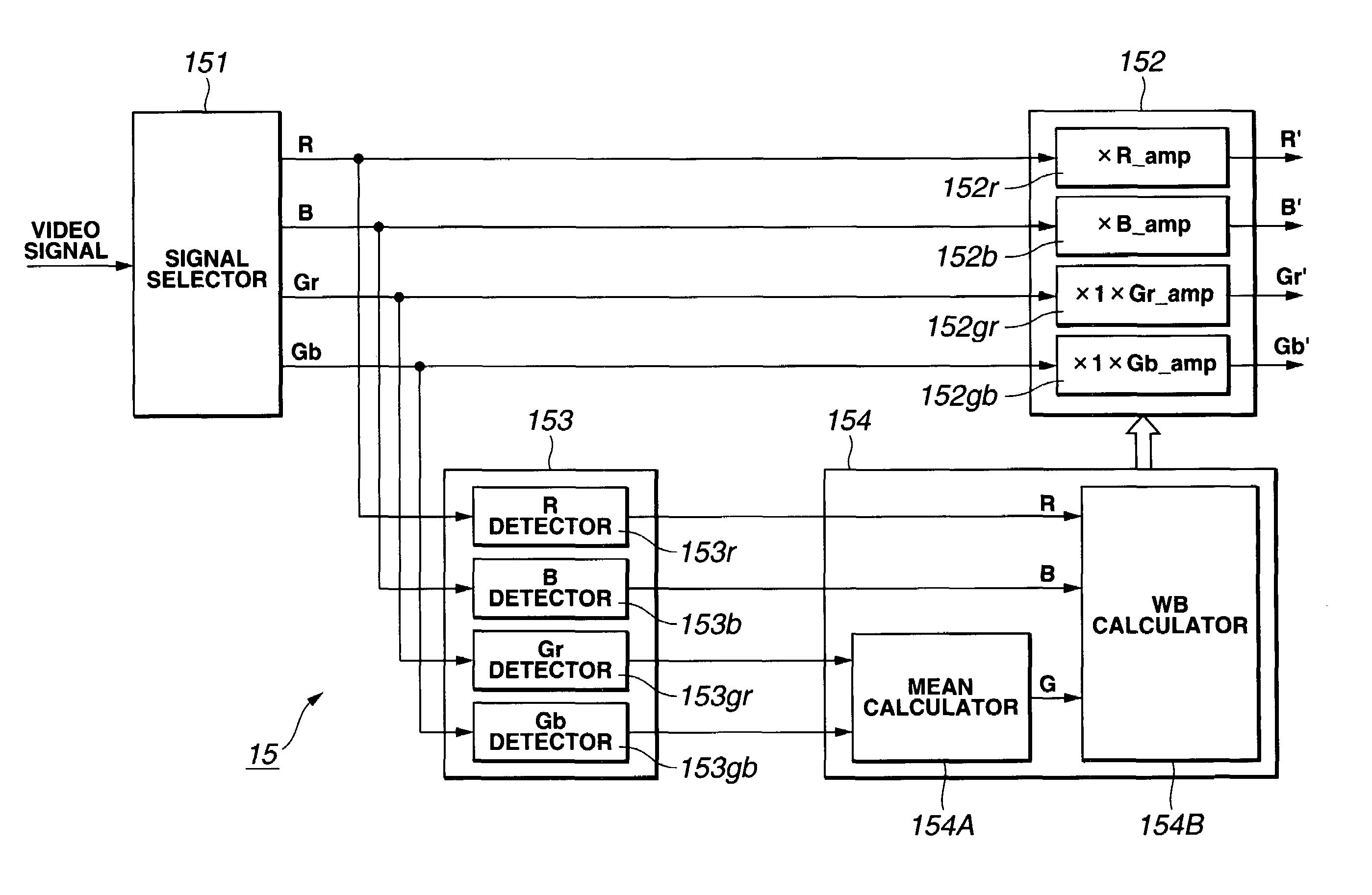
Color imaging by independently controlling gains of each of R, Gr, Gb, and B signals
a color imaging and gain control technology, applied in the field of single-chip color imaging apparatus and method, can solve the problems of horizontal stripe-like noise, difference in amplitude between luminance signals,
- Summary
- Abstract
- Description
- Claims
- Application Information
AI Technical Summary
Benefits of technology
Problems solved by technology
Method used
Image

Examples
Embodiment Construction
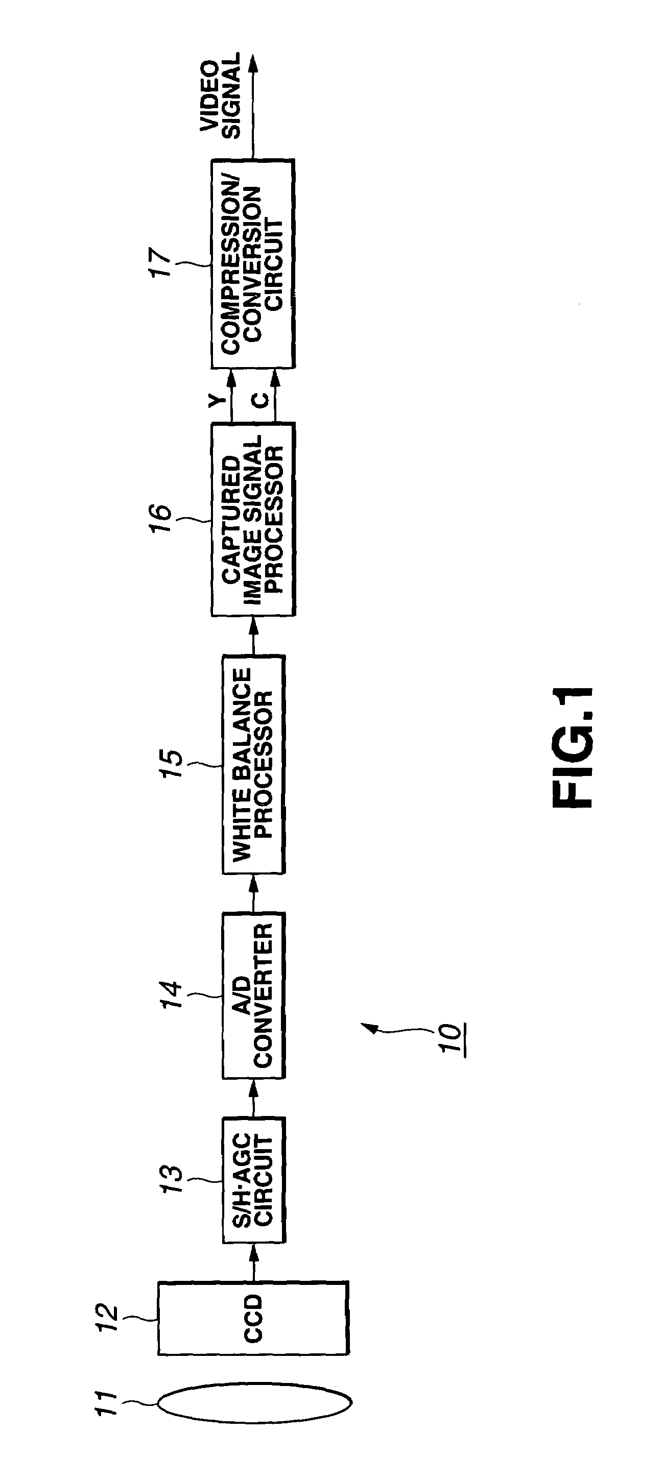
[0031]Referring now to FIG. 1, there is illustrated in the form of a block circuit diagram the solid-state color imaging apparatus according to the present invention. The solid-state color imaging apparatus is generally indicated with a reference 10.
[0032]The solid-state color imaging apparatus 10 is a single-chip solid-state color imaging apparatus including an imaging optical system 11, a CCD (Charge Coupled Device) 12 having an image sensing layer on which an image of an object is formed by the imaging optical system 11, an S / H•AGC circuit 13, an A / D converter 14 supplied with a captured image signal taken from the CCD 12 via the S / H•AGC circuit 13, a white balance processor 15 supplied with a digital captured image signal from the A / D converter 14, a captured image signal processor 16 supplied with the captured image signal adjusted in white balance by the white balance processor 15, and a compression / conversion circuit 17 supplied with a luminance signal Y and chrominance signa...
PUM
 Abstract
Description
Claims
Application Information