Actively-supported multi-degree of freedom steerable mirror apparatus and method

a technology of active support and steerable mirrors, applied in the field of optical techniques, can solve the problems of adversely affecting optical and structural performance, limited range of motion of mirror surfaces, limited range of motion, etc., and achieve the effect of large angular range of motion and dynamic range, and high precision

Active Publication Date: 2006-03-07
LOCKHEED MARTIN CORP
View PDF3 Cites 54 Cited by
  • Summary
  • Abstract
  • Description
  • Claims
  • Application Information

AI Technical Summary

Benefits of technology

[0014]Numerous benefits are achieved using the present invention over conventional techniques. For example, in an embodiment according to the present invention, the center of mass of the mirror is aligned with the center of rotation. This benefit is present even when the mirror has a reflective surface in the shape of an annulus. In alternative embodiments, the center of mass is located at a position between the bottom of the mirror and the mirror's reflective surface. Additionally, steerable mirrors according to embodiments of the present invention provide both a large angular range of motion and dynamic range along with high precision. Moreover, steerable mirrors according to embodiments of the present invention provide for motion of the mirror in multiple degrees of freedom. This flexibility in available mirror motions provides a system that incorporates both active piston or focus control, enabling the mirror to move in a manner analogous to rotation about the front surface of the mirror. Also, embodiments according to the present invention are useful in interferometric applications which conserve optical path lengths for given portions of the optical system. Depending upon the embodiment, one or more of these benefits may exist. These and other benefits have been described throughout the present specification and more particularly below.

Problems solved by technology

The mirror surface is limited in a range of motion, which is undesirable.
Moreover, the range of motion is limited in the direction perpendicular to the support base.
Weakening of the mirror substrate may result in undesirable deformations of the mirror surface, adversely impacting optical and structural performance.

Method used


Image

  • Actively-supported multi-degree of freedom steerable mirror apparatus and method
  • Actively-supported multi-degree of freedom steerable mirror apparatus and method
  • Actively-supported multi-degree of freedom steerable mirror apparatus and method

Examples


Embodiment Construction

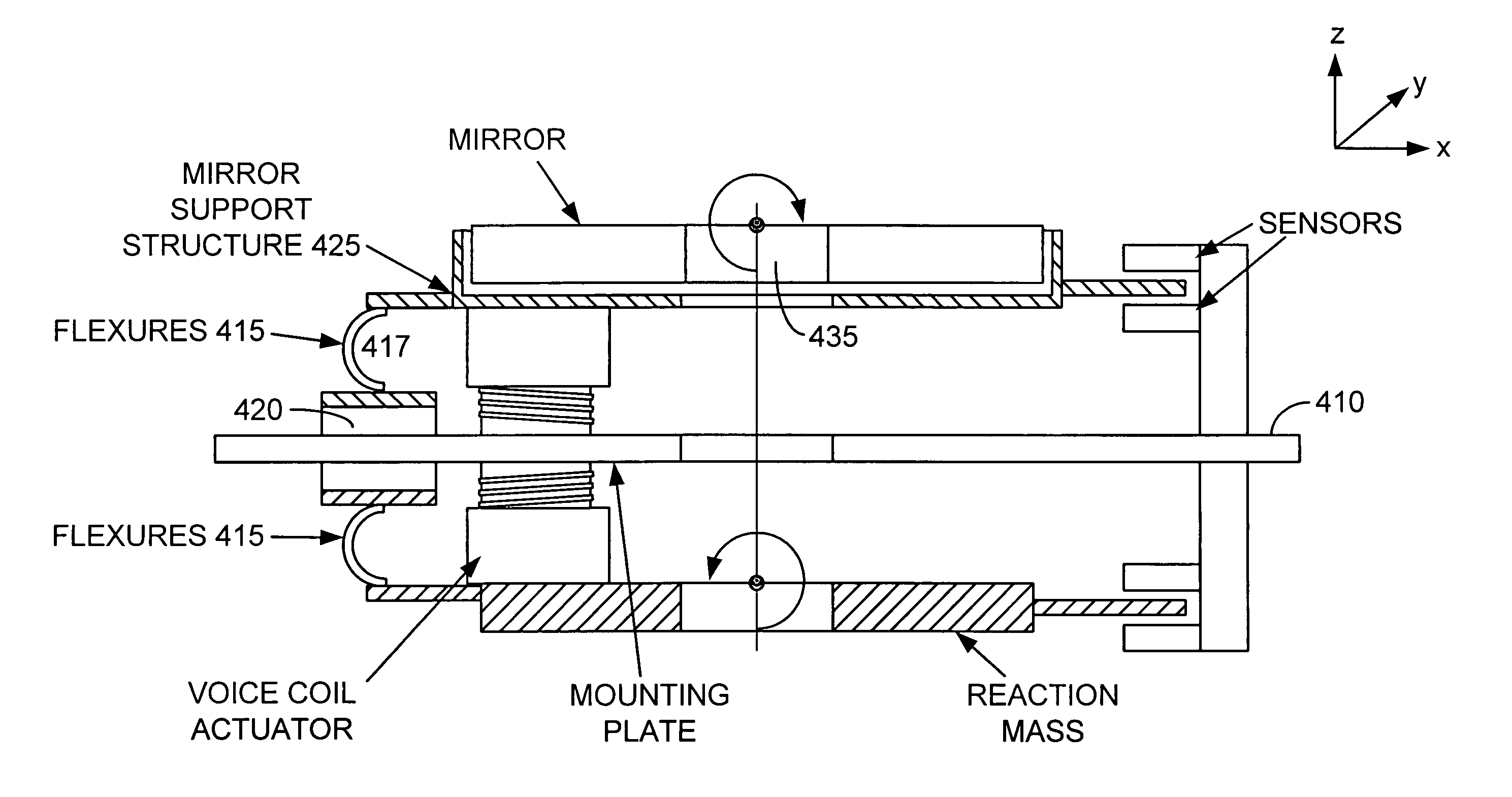
[0029]According to the present invention, optical assemblies are provided. More particularly, the invention provides a method and structure for fabricating and controlling a steerable mirror. Merely by way of example, the invention has been applied to a steerable mirror featuring a reflective surface in the shape of an annulus as can be found in telescopes commonly referred to as Cassegrain telescopes. The method and structure can be applied to other applications as well such as air or space borne telescopes, laser systems, laser radar systems, and the like.

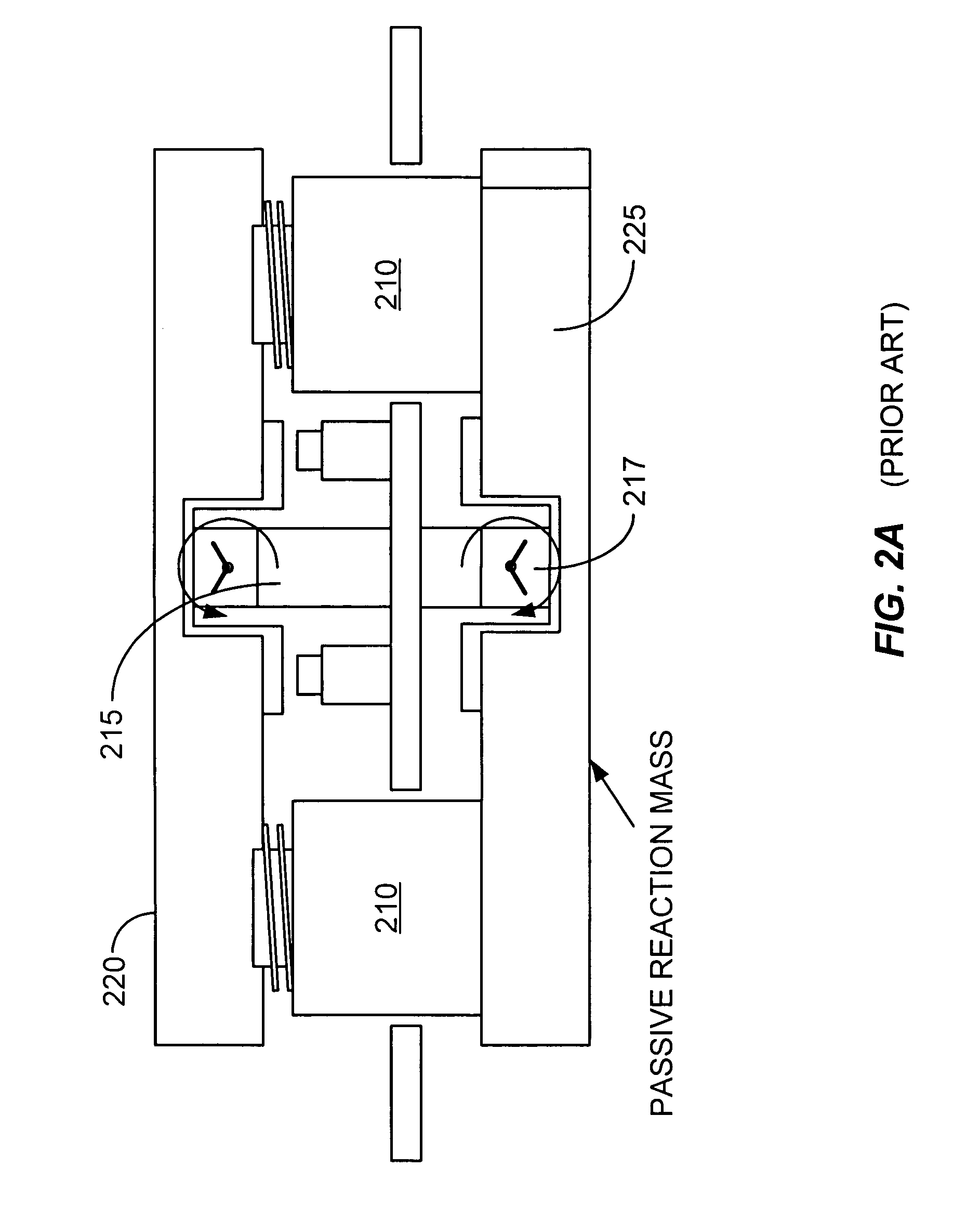
[0030]FIG. 2A is a simplified schematic diagram of a conventional steerable mirror mounted in combination with a passive reaction cancellation mass. Often, in precision optical systems, forces produced by the actuators 210, employed to move the mirror 220, will produce reaction forces that may excite unwanted structural vibrations. A passive reaction cancellation system as illustrated in FIG. 2A provides an equal and opposite pas...


PUM


Abstract

A steerable mirror assembly, the assembly comprising a mounting plate and a mirror with a mounting surface and a reflective surface. The assembly further comprising at least one flexible connector coupled between the mounting plate and a peripheral portion of the mirror. The flexible connector is adapted to allow the mirror to move within a predetermined range along an axis perpendicular to the surface of the mirror and adapted to allow tilting of the mirror. The assembly also comprising at least one moveable support member coupled between the mounting plate and the mounting surface of the mirror. The moveable support member provides mechanical support to the mirror and is adapted to move the mirror within a predetermined range along an axis perpendicular to the surface of the mirror and adapted to allow tilting of the mirror. The assembly additionally comprising at least one position sensor.

Description

CROSS-REFERENCES TO RELATED APPLICATIONS[0001]This non-provisional application claims priority to U.S. provisional application No. 60 / 441,854 filed Jan. 21, 2003. This provisional patent application is incorporated by reference herein for all purposes.BACKGROUND OF THE INVENTION[0002]This present invention relates generally to optical techniques. More particularly, the invention provides a method and structure for fabricating and controlling a steerable mirror. Merely by way of example, the invention has been applied to a steerable mirror featuring a reflective surface in the shape of an annulus as can be found in telescopes commonly referred to as Cassegrain telescopes. The method and structure can be applied to other applications as well such as air or space borne telescopes, laser systems, laser radar systems, and the like.[0003]Conventional steerable mirrors have been used in a wide variety of applications. Certain applications include spatial chopping secondary mirrors on infra...

Claims


Application Information

Patent Timeline
Patent Type & Authority Patents(United States)
IPC IPC(8): G02B26/00
CPCG02B7/1821G02B26/105G02B26/0816
Inventor LORELL, KENNETH ROYAUBRUN, JEAN-NOEL
Owner LOCKHEED MARTIN CORP
Why Eureka
Try Eureka