Detection of track misregistration within user data channel

a user data channel and track technology, applied in the direction of track following on disks, magnetic recording, instruments, etc., can solve the problems of reducing the amount of disk space for user data storage, only having a position error signal (pes), and no method for accurately determining

Inactive Publication Date: 2006-03-07
AGENCY FOR SCI TECH & RES
View PDF2 Cites 27 Cited by
  • Summary
  • Abstract
  • Description
  • Claims
  • Application Information

AI Technical Summary

Benefits of technology

[0012]The present invention provides a method for detecting and estimating position information in a data storage device with continuous position information in the data sector. A rough position of the transducer or read / write head is determined through demodulation of the readback signal from the servo sector. Once this rough position is determined, demodulation of the readback signal from the data sector is triggered allowing continuous tracking of the position of the transducer when it is operating in the data sector. This is made possible through a writing process where the readback signals from the written data in the data sector are distinct from readback signals from adjacent tracks.
[0014]In one embodiment of the present invention, the method provides for receiving and writing of user data in the data sector on a disk once the track address is determined. The user data information is written at different bit intervals through adjusting the timing in a programmable clock generator to vary time interval such that the written data information has a readback signal with either its frequency or phase differing from a readback signal from an adjacent track. This can be achieved by an increase or decrease in the time interval to change the frequency of the data information signal during the writing process or by a shift in the time interval through starting the write process at a different phase of the same signal frequency. This difference of the frequencies and phases allows the data information in each data sector to be extracted with little interference from readback signals of stored information in adjacent tracks. Based on this information, the position of the head, whether it is shifted to the left or right side of the track center can be determined. The time interval setting for writing the user data information at a particular bit interval of a track is noted and stored in a look-up table in a program memory device in the disk drive and is retrieved when writing and readback operations are performed on a track. The time interval setting information can also be stored in a preamble of the data sector. Accordingly, the method provides for accurate estimation of position information of the transducer even with an increase in the track density.
[0019]In yet another aspect of the present invention, the method is implemented in a system where an algorithm for writing data information in a data sector such that the written data information has a readback signal with a different frequency pattern from adjacent tracks, an algorithm for computing servo information from servo sector for a Position Error Signal (PES) enables coarse positioning and track seeking operation with the help of track ID information from the Gray Code in the servo sector, and an algorithm for estimating position information from user data channel to provide a smoothed average value coefficient through the readback signals from the data sector for more precise track following operation within the user data area. The system of the present invention also incorporates the use of a transition detection system in its algorithm to enable the detection of magnetic transitions of the storage media. Such a detection system helps to activate the demodulation step in the algorithm for estimating the position information from the data sector. In an ideal situation, the selected frequency pattern would be dipulses with distinct transition points.

Problems solved by technology

One problem with the sector servo method is that the position error signal (PES) is only available when the head is reading the servo sector.
When the head is at the data sector, there is no method available for accurately determining that the head is on track or on track center throughout read / write operations.
Unfortunately, if the number of servo sectors is increased, the amount of disk space for the storage of user data is reduced.
Such disturbances contribute to the degrading of PES and reduce servo performance and available data storage space.
Other methods were also unable to overcome having to compromising data storage space in a disk.
While this method allows continuous PES in the user data sector to facilitate precise track following, the dividing of user data into 2-bit groups and further encoding into 8-code bits limit the number of bit cell reserved for storing user data bits, hence limiting the storage space in the disk drive.
This method provides continuous and simultaneous track following but at the expense of disk space which is used for storing the additional servo tracks.
However, this method does not provide a continuous PES in the user data sector and therefore does not provide for continuous track following in the user sector.

Method used


Image

  • Detection of track misregistration within user data channel
  • Detection of track misregistration within user data channel
  • Detection of track misregistration within user data channel

Examples


Embodiment Construction

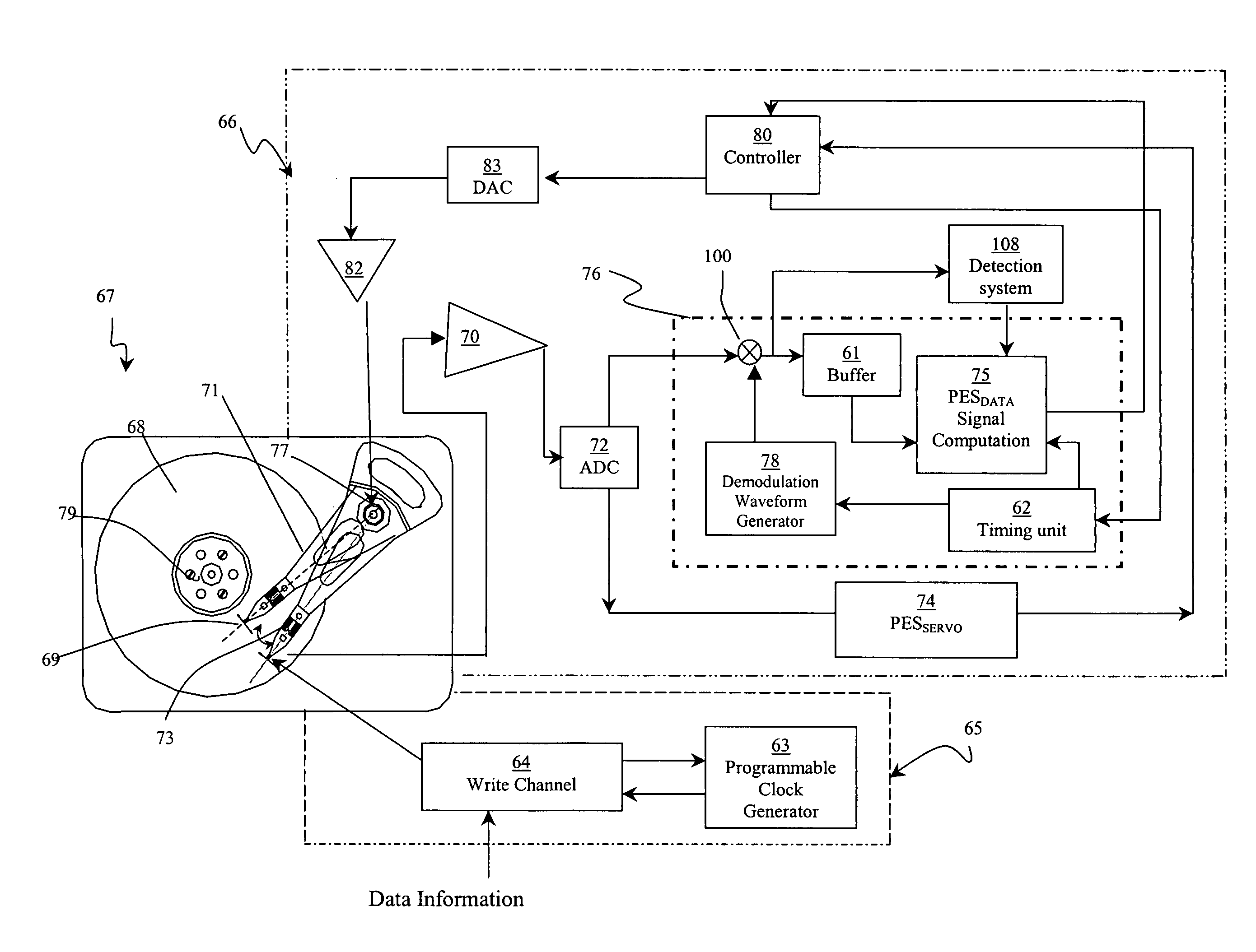
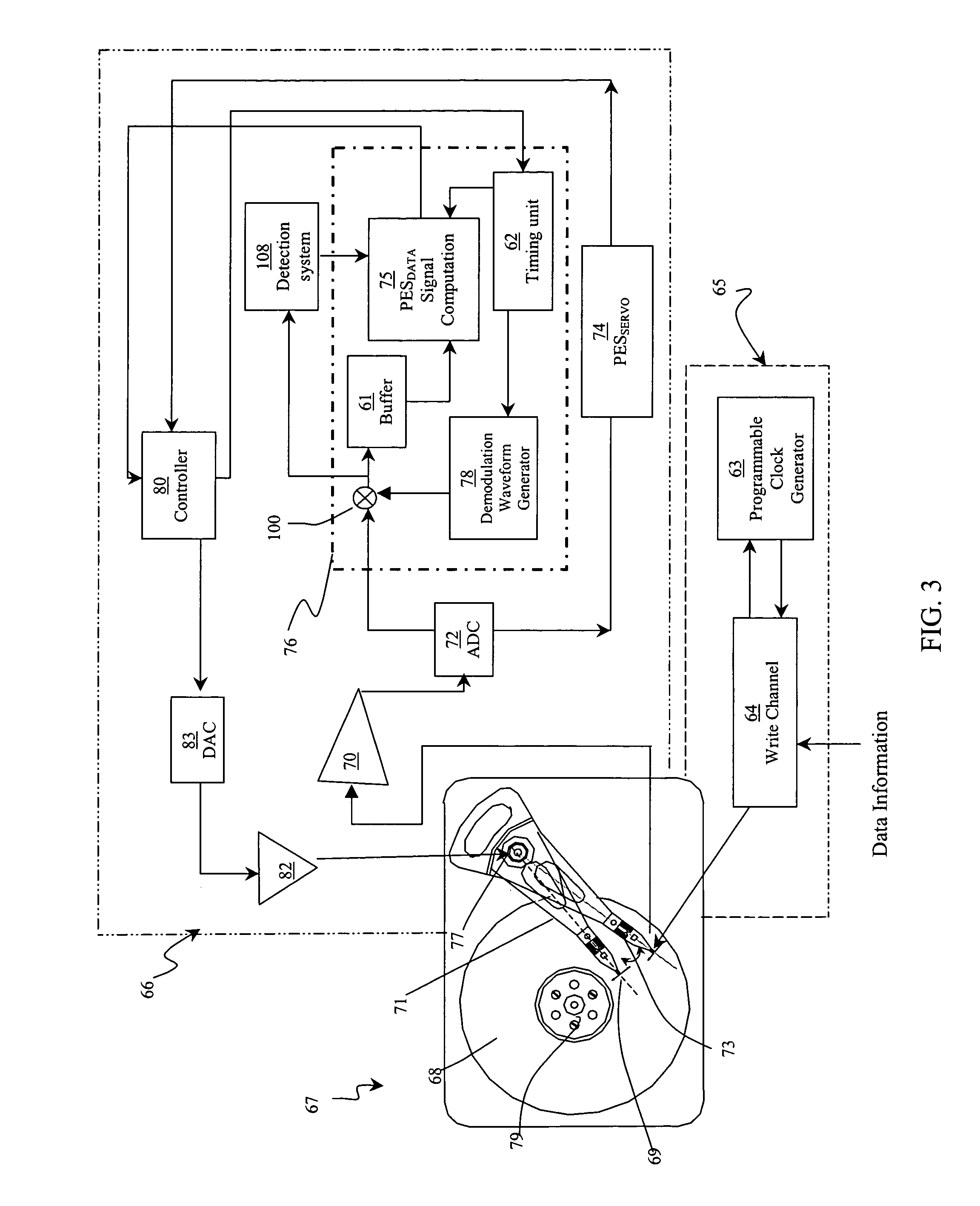
[0041]FIG. 3 illustrates an embodiment of the present invention that includes a disk drive 67 connected to a first circuit 65 for writing data information in a data sector of a track on the disk 68 and a second circuit 66 for detecting track misregistration. The disk drive 67 includes a disk 68 mounted on a spindle 79 for rotating the disk 68, and an actuator 71 on which a transducer 69 is mounted to store and retrieve data information on the disk 68. The transducer 69 is also commonly referred to as read / write head.

[0042]The first circuit 65 includes a write channel 64 and a programmable clock generator 63. In the first circuit 65, raw data information to be written and stored in a data sector of a track on a disk is passed through the write channel 64 into the programmable clock generator 63 where the data information signal undergoes a frequency change or phase shift by applying a change in the time interval setting in the clock generator 63. The altered signal from the programma...


PUM

PropertyMeasurementUnit
frequencies F1aaaaaaaaaa
frequencyaaaaaaaaaa

Abstract

A method for computing position error signal information of a transducer in a data storage system provides for different readback signals between adjacent tracks. The method involves a computation to obtain coarse position information from the servo bursts signals for track seeking and a computation to obtain a position indicator from the user data sector for more precise track following within the user data sector.

Description

TECHNICAL FIELD[0001]This invention relates to a method, system and apparatus of position control of a component in an assembly, such as a transducer in a hard disk drive, which is required to move in relation to another component. More particularly, the invention relates to controlling the position of the transducer during track following.BACKGROUND OF THE INVENTION[0002]A disk drive 10 operates with a transducer 18 to read and write data on a disk 12, which is mounted on a spindle motor 11 in the disk drive 10 as shown in FIG. 1. The transducer 18 is also commonly referred to as a read / write head. The disk 12, illustrated in greater detail in FIG. 2, includes a number of concentric tracks 28 that are divided into radial sectors 30 so that data can be stored according to the track and sector addresses.[0003]The disk 12 spins about the spindle motor 11 allowing the transducer 18 to change its position from sector to sector on the same track. The transducer 18 is moved across the dis...

Claims


Application Information

Patent Timeline
Patent Type & Authority Patents(United States)
IPC IPC(8): G11B5/596
CPCG11B5/596G11B5/59655
Inventor WONG, WAI EEGUO, GUOXIAOAL MAMUN, ABDULLAHYE, WEICHUNZHANG, JINGLIANG
Owner AGENCY FOR SCI TECH & RES
Why Eureka
Try Eureka