
Composite structural components containing thermotropic liquid crystalline polymer reinforcements for optical fiber cables

a technology of thermotropic liquid crystalline polymer and composite materials, which is applied in the direction of cladding optical fibre, optical waveguide light guide, textiles and paper, etc., can solve the problems of high cost, inability to practically incorporate special processing equipment into optical fiber cable manufacturing processes, and inability to melt aramid lcps. conventionally, to achieve the effect of low thermal expansion coefficient, good processability and good strength

Inactive Publication Date: 2006-03-07
DRAKA COMTEQ BV
View PDF28 Cites 34 Cited by
  • Summary
  • Abstract
  • Description
  • Claims
  • Application Information

AI Technical Summary

Benefits of technology

The present invention provides a new way to make a component for an optical fiber cable. This component is made from a composite material containing thermotropic liquid crystalline polymer reinforcements. The resulting material has high strength, low thermal expansion, and good processability. The method involves co-extruding conventional thermoplastic polymer and thermotropic liquid crystalline polymer to create a structural component with fibrils dispersed in a thermoplastic matrix. The fibrils have a unique structure and size that enhances the properties of the resulting material.

Problems solved by technology

Aramid fibers or yarns are commonly used as reinforcing materials because they offer the best combination of mechanical properties and weight, but these materials are also characterized by a high cost.
However, due to very high melting points of the polymeric materials used, conventional melt processing of aramid LCPs is not possible.
This special processing equipment cannot be practically incorporated into an optical fiber cable manufacturing process.
The addition of components or processing steps adds to the manufacturing costs and to the complexity of the production procedure.

Method used


Image

  • Composite structural components containing thermotropic liquid crystalline polymer reinforcements for optical fiber cables
  • Composite structural components containing thermotropic liquid crystalline polymer reinforcements for optical fiber cables
  • Composite structural components containing thermotropic liquid crystalline polymer reinforcements for optical fiber cables

Examples


Embodiment Construction

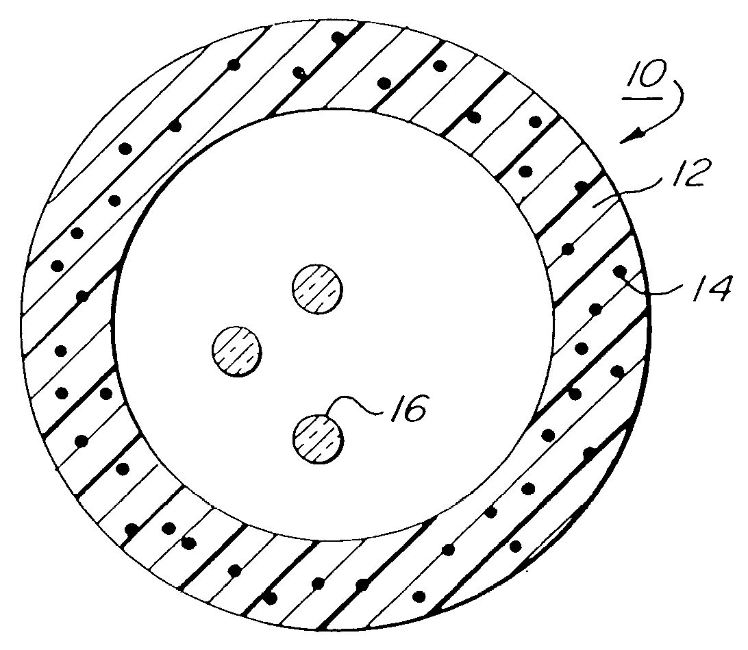
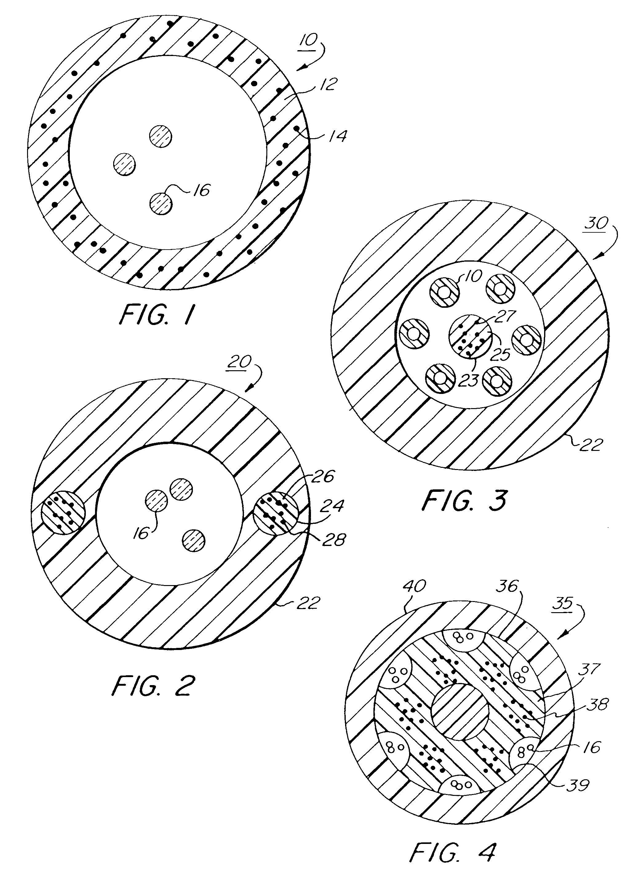
[0024]FIG. 1 illustrates a typical optical fiber cable buffer tube for an optical fiber cable of the loose tube variety. According to the present invention, the buffer tube 10 illustrated in FIG. 1 is formed from a composite material comprising a thermoplastic matrix material 12 having thermotropic liquid crystalline polymer (TLCP) reinforcement fibrils 14 incorporated therein. The buffer tube 10 houses optical fibers 16. FIG. 2 illustrates a cable structural member, like a buffer tube, comprising a jacket 22 having rod-like reinforcement members 24 incorporated therein. The reinforcement members 24 are formed from a thermoplastic matrix material 26 containing TLCP reinforcement fibrils 28. FIG. 3 illustrates a stranded optical fiber cable 30 having a plurality of buffer tubes 10 housing optical fibers (not shown) contained within an outer jacket 22. A strength member 23 is also contained within the outer jacket 22. The strength member is formed from a thermoplastic matrix 25 having...


PUM

PropertyMeasurementUnit
lengthaaaaaaaaaa
weight percentaaaaaaaaaa

Abstract

A process for producing an optical fiber cable composite structural component, such as reinforcing members, buffer tubes, filler rods, jackets, and slotted cores, is disclosed. The composite structural components are produced by co-extruding a thermotropic liquid crystalline polymer (TLCP) and a thermoplastic matrix material into the composite structural component so that TLCP reinforcing fibrils are dispersed in the thermoplastic matrix material. The TLCP reinforcing fibrils undergo a high level of process induced orientation, are provided with a high aspect ratio, and small diameters. The composite structural component has a high modulus. The TLCP reinforcing fibrils may be made continuous or discontinuous.

Description

CROSS REFERENCE TO RELATED APPLICATIONS[0001]This application is a divisional application of and claims priority to U.S. application Ser. No. 10 / 105,925 filed Mar. 25, 2002 which is a divisional of U.S. application Ser. No. 09 / 027,693 filed Feb. 23, 1998 (now abandoned).BACKGROUND OF THE INVENTION[0002]1. Field of the Invention[0003]The present invention relates to optical fiber cables and structural members for optical fiber cables. More particularly, this invention relates to optical fiber cable structural members formed from composite materials containing thermotropic liquid crystalline polymer reinforcements which are formed in-situ with a matrix.[0004]2. Description of the Prior Art[0005]Optical fiber cables have been in use in the communications industry for a number of years to transmit information at very high rates over long distances. In an optical fiber cable the information is carried in the form of light signals through glass fibers with diameters on the order of 100 μm...

Claims


Application Information

Patent Timeline
Patent Type & Authority Patents(United States)
IPC IPC(8): G02B6/44C08J5/04C08K3/00C08K5/098C08L67/02C08L67/03C08L101/00D02G3/00
CPCC08J5/046C08L23/02C08L23/06C08L23/10C08L67/00C08L67/02C08L77/00G02B6/4429G02B6/443Y10T428/2933C08J2323/10C08K3/0033C08K5/0083C08K5/098C08L67/03C08L2205/08C08L2205/12C08J2323/02Y10T428/2929C08L2666/18C08L2666/02C08K2201/016C08K3/013G02B6/44384
Inventor RISCH, BRIAN G.
Owner DRAKA COMTEQ BV
Learn More