Apparatus and method for carrying substrate

Inactive Publication Date: 2006-03-14
SHIBAURA MECHATRONICS CORP
View PDF12 Cites 3 Cited by
  • Summary
  • Abstract
  • Description
  • Claims
  • Application Information

AI Technical Summary

Benefits of technology

[0016]According to the first, the third, the fourth and the fifth aspect of the present invention, the extension support member can be connected to the substrate support member attached to the transfer mechanism or the like, in order to support a substrate in cooperation with the substrate support member. Therefore, it is possible to cope with the change of the sizes of the substrates resulting from the change of the types of flat panel displays or the like, by connecting the extension support member to or disconnecting the same from the substrate support member. Only the comparatively light part, i.e., the extension support member, needs to be changed instead of changing the entire structure for supporting a substrate, i.e., the substrate support member and the extension support member, to carry a large substrate. Since the operator is able to handle the extension support member easily, time necessary for conducting changing work for changing the types of flat display panels or the like can be reduced.
[0017]According to the first aspect of the present invention, the substrate support member and the extension support member can be easily connected together simply by joining the engaging part formed in the peripheral part of the support body of the substrate support member to the end part of the extension support member. The suction passage of the substrate support member and that of the extension support member can be connected by a connecting structure when the substrate support member and the extension support member are combined together. Thus both the respective suction passages of the substrate support member and the extension support member can be easily connected with both the respective suction members of the substrate support member and the extension support member being in suction by the same vacuum source for suction. Since

Problems solved by technology

Therefore, changing the substrate support memb

Method used


Image

  • Apparatus and method for carrying substrate
  • Apparatus and method for carrying substrate
  • Apparatus and method for carrying substrate

Examples


first embodiment

[0029]A substrate carrying device in a first embodiment of the present invention will be described with reference to FIGS. 1A to 5B.

[0030]First, the general construction of a part-mounting apparatus relating to the present invention will be described with reference to FIGS. 5A and 5B.

[0031]Referring to FIGS. 5A and 5B, a part-mounting apparatus for mounting an electronic part 42 on a glass substrate 41 is provided with a pressing tool 76 and a transfer mechanism 61 for moving the pressing tool 76. The electronic part 42 held on the pressing tool 76 by suction is mounted on the glass substrate 41. The transfer mechanism 61 has a Z-axis transfer unit 62 for moving the pressing tool 76 in vertical directions, i.e., directions along a Z-axis, and a Y-axis transfer unit 63 for moving the pressing tool 76 in horizontal directions, i.e., directions along a Y-axis. The electronic part 42 held on the pressing tool 76 by suction can be carried from a transfer position T to a mounting position...

second embodiment

[0060]A substrate carrying device in a second embodiment of the present invention will be described with reference to FIGS. 6A and 6B. The second embodiment excluding a substrate carrying device is identical with the first embodiment shown in FIGS. 1A to 5B. In the second embodiment, parts like or corresponding to those of the first embodiment shown in FIGS. 1A to 5B are denoted by the same reference characters and the description thereof will be omitted.

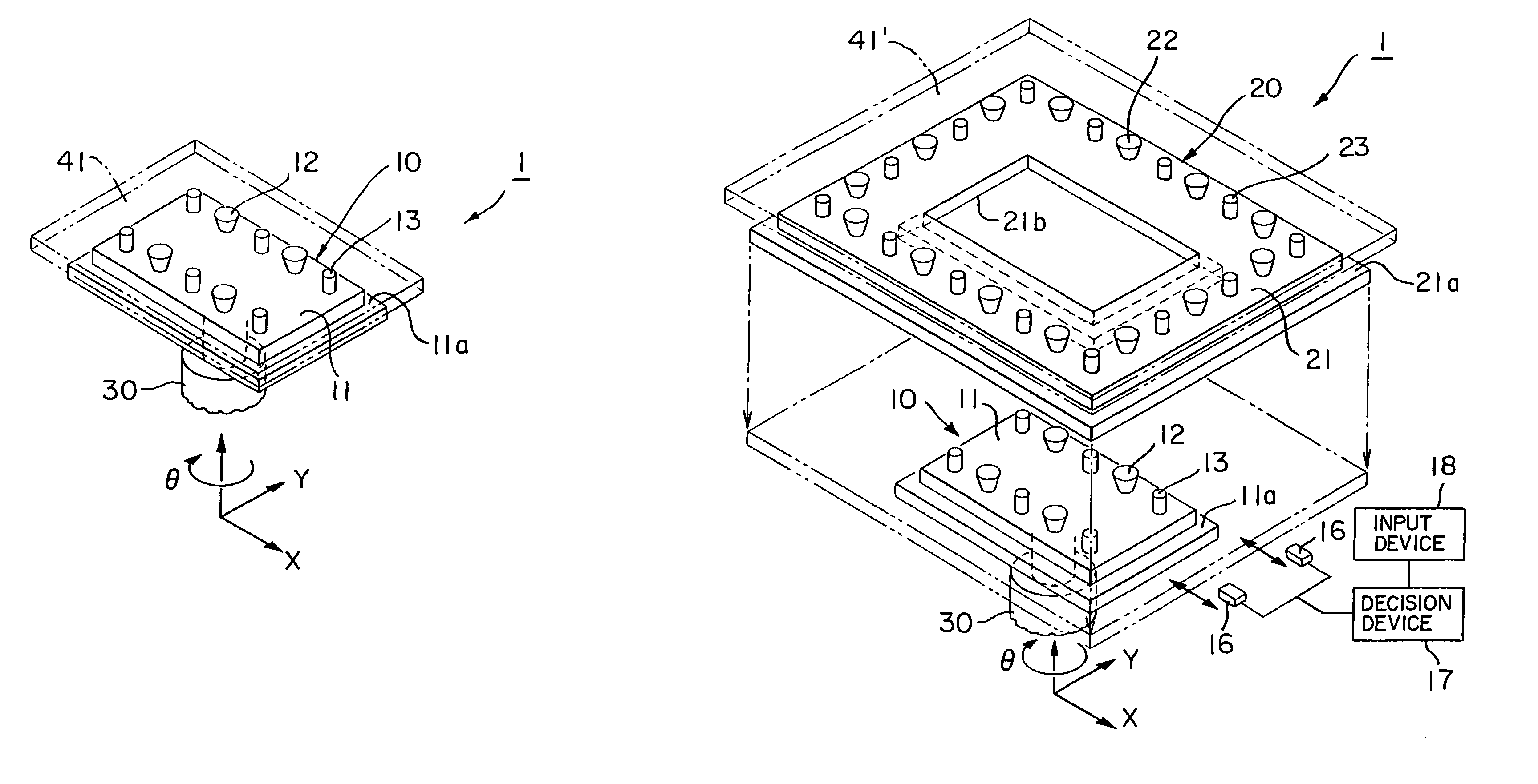
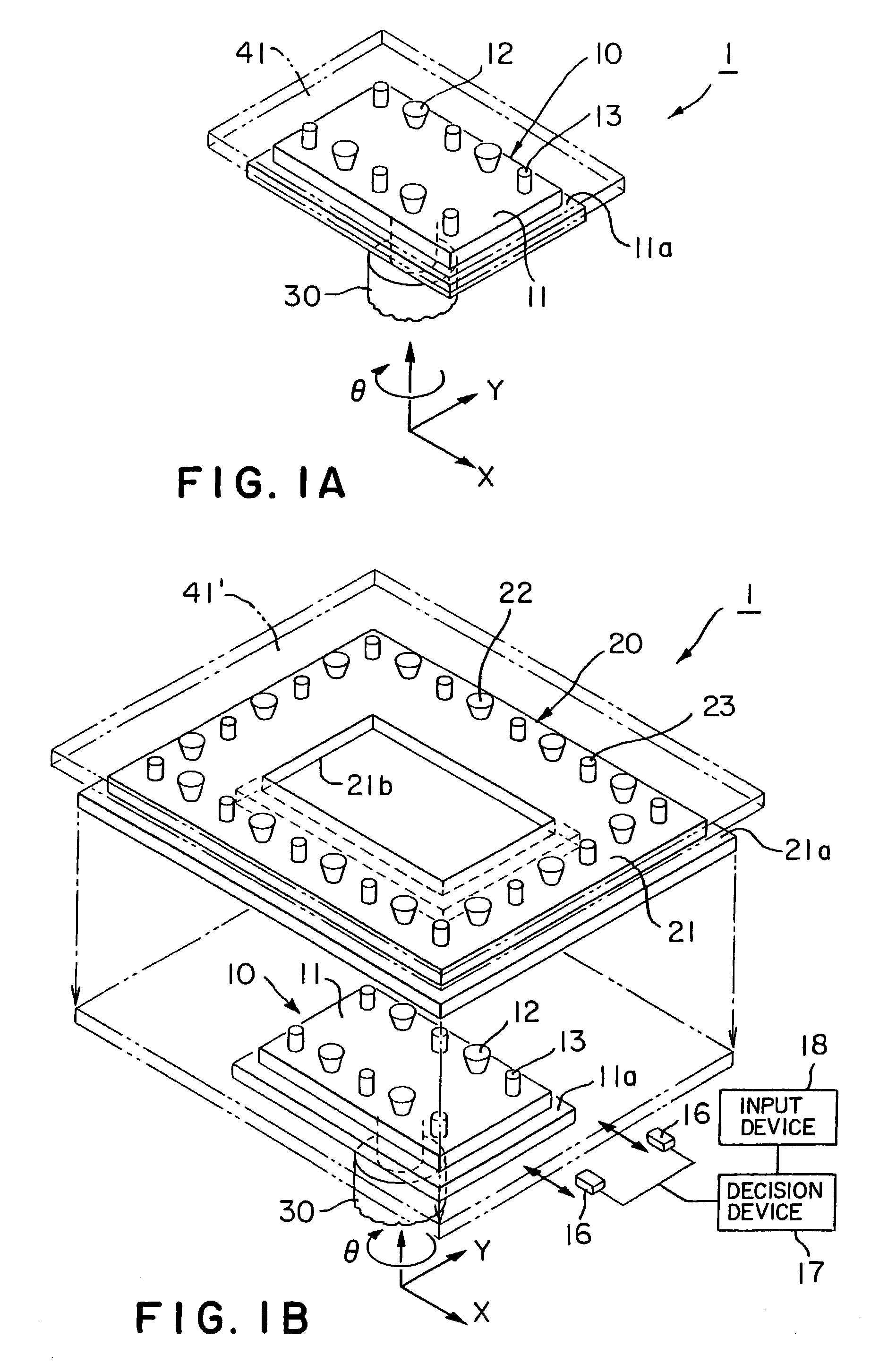
[0061]Referring to FIGS. 6A and 6B, a substrate carrying device 35 in a second embodiment of the present invention has a transfer mechanism 30 capable of translational movement and rotation in an XY-plane, and a substrate support member 36 attached to the transfer mechanism 30 to support a glass substrate thereon.

[0062]The substrate support member 36 has a fixed support part (first support part) 37, and movable support parts (second support parts) 38 connected to the fixed support part 37 by a sliding mechanism 39 for movement relat...

third embodiment

[0066]A substrate carrying device in a third embodiment of the present invention will be described with reference to FIG. 7, in which parts like or corresponding to those of the first embodiment shown in FIGS. 1A to 5B are denoted by the same reference characters and the description thereof will be omitted. The substrate carrying device in the third embodiment is similar to the first embodiment shown in FIGS. 1A to 5B, except that the substrate carrying device in the third embodiment uses only an extension support member for supporting a glass substrate.

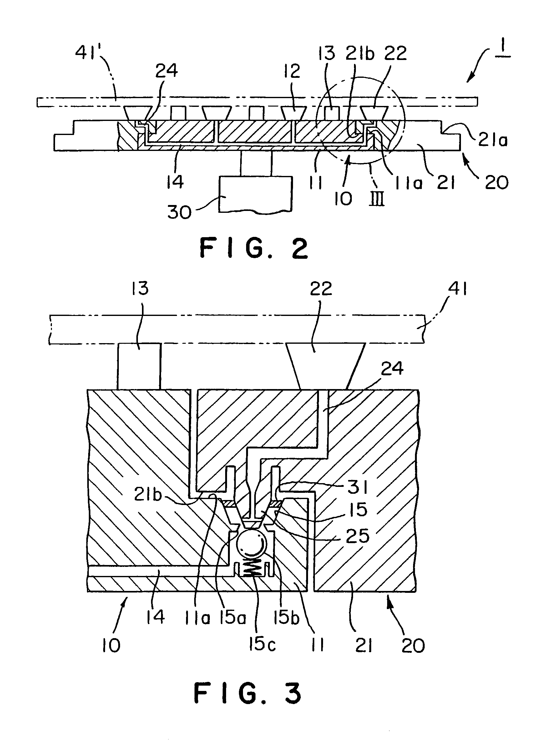
[0067]Referring to FIG. 7, the substrate carrying device in the third embodiment has a substrate support member 10 and an extension support member 20, and only the extension support member 20 is provided with suction pads 22 and flatness adjusting mechanisms 23.

[0068]More concretely, three extension support members 20a, 20b and 20c respectively having different shapes are reserved, and one of the extension support members 20a, 20b an...


PUM

PropertyMeasurementUnit
Timeaaaaaaaaaa
Sizeaaaaaaaaaa

Abstract

A substrate carrying device reduces time necessary for conducting changing work for changing the types of flat panel displays or the like. A substrate support member (10) has a support body (11) provided with an outer peripheral part (11a), which is joined to an inner peripheral part (21b) of an extension support member (20) to connect the substrate support member (10) to the extension support member (20). Only by the substrate support member (10) is used for supporting a small glass substrate (41) to carry the small glass substrate (41). A combination of the substrate support member (10) and the extension support member (20) is used for supporting a large glass substrate (41′) to carry the large glass substrate (41′).

Description

TECHNICAL FIELD[0001]The present invention relates to a part-mounting apparatus and a part-mounting method to be used in fabricating a flat panel display or the like represented by a liquid crystal display. More particularly, the present invention relates to a substrate carrying device and a substrate carrying method for transferring substrates between processes.BACKGROUND ART[0002]A conventional part-mounting apparatus for use in fabricating a flat panel display represented by a liquid crystal panel mounts a flexible electronic part, such as a FPC (flexible printed circuit), a COF (chip-on-film) circuit, a TCP (tape carrier package) or the like on a glass substrate.[0003]Generally, such a part-mounting apparatus includes a substrate carrying device for positioning a glass substrate at a working position and carrying a glass substrate between working positions.[0004]FIGS. 8A and 8B show a conventional substrate carrying device 50. As shown in FIG. 8A, the substrate carrying device 5...

Claims


Application Information

Patent Timeline
IPC IPC(8): B23P19/00B65G49/06H01L21/677H01L21/68H01L21/687
CPCB65G49/061H01L21/6835H01L21/68707H01L21/6875H01L21/68778B65G2249/04Y10T29/53178Y10T279/11Y10T29/53261Y10T29/53174Y10T29/53183Y10T29/5313B65G47/91B65G49/067B65G2201/022G02F1/1303H01L21/67173H01L21/67745H05K13/0061
Inventor OGIMOTO, SHINICHI
Owner SHIBAURA MECHATRONICS CORP
Why Eureka
Try Eureka