Method for underwater transportation and installation or removal of objects at sea

a technology for underwater transportation and installation or removal of objects, applied in underwater structures, artificial islands, buoys, etc., can solve the problems of unfit, inadequate or very expensive conventional methods, and large dimensions and weight of objects to be installed or removed from offshore sites, so as to improve weather criteria, reduce operation costs, and be less weather-sensitive

Inactive Publication Date: 2006-03-14
AKER MARINE CONTRACTORS
View PDF12 Cites 23 Cited by
  • Summary
  • Abstract
  • Description
  • Claims
  • Application Information

AI Technical Summary

Benefits of technology

[0013]When applying the invention one achieves a number of advantages compared to conventional methods. In particular, one avoids the problems and weather restrictions associated with an offshore lift from deck and subsequent lowering through the splashzone / sea surface. Avoiding using crane vessels and improving the weather criteria for the installation will also result in a major reduction in cost for the operation, and the invention is in principle independent of dimensions and weight of the object to be transported and installed. Further, the transport to destination is safer and less weather sensitive since the object is suspended from a slender buoyancy unit and is independent of the installation vessel during transport. The buoyancy unit has a small and constant waterplane area and acts as a heave compensator, thereby reducing the dynamic loads in the object and the suspension arrangement between the object and buoyancy unit. The method can be based on using the same vessel for both the tow and the installation or recovery, and a minimum of equipment is needed. This means that any vessel that satisfies the basic capacity requirements may be used, which increases vessel availability, opens for using low cost vessels and reduces vessel mobilisation time.

Problems solved by technology

Some of the objects that are to be installed or removed from the offshore sites are relatively complicated with large dimensions and weights.
One is often dependent on costly vessels and equipment, and the availability of such vessels may also be poor.
Based on these aspects there is a need to develop new and alternative methods for transport and installation / removal of objects, as conventional methods become unfit, inadequate or very expensive.
Such operations set high demands to crane capacity and deck space, and can be very weather sensitive operations depending on type of object to be installed and the motion characteristics of the installation vessel(s).
They further require costly construction vessels and potentially tying them up for long periods of time depending on weather.
The lowering of the pipeline is started from one end, and if the water is deep, a substantial part of the pipeline will be suspended in the still floating part before the first end reaches the bottom, thus subjecting part of the pipeline to very substantial bending loads and possibly also causing the lowering process to become out of control.
In any case, such recovery work would be quite complicated, particularly at greater depths.
Besides, the installation of temporary tension legs for the barge adds considerably to the complexity and cost of this method, which also seems limited to shallow waters and good weather conditions.
This method is limited to water depths where jackets may be used and where the object may be raised one end at a time.
The barge will have a substantial water line cross-section and therefore respond to wave motion, and with the object suspended in releasable rocker beams it will not be possible to lower the object in a controlled manner after its release.

Method used


Image

  • Method for underwater transportation and installation or removal of objects at sea
  • Method for underwater transportation and installation or removal of objects at sea
  • Method for underwater transportation and installation or removal of objects at sea

Examples


Embodiment Construction

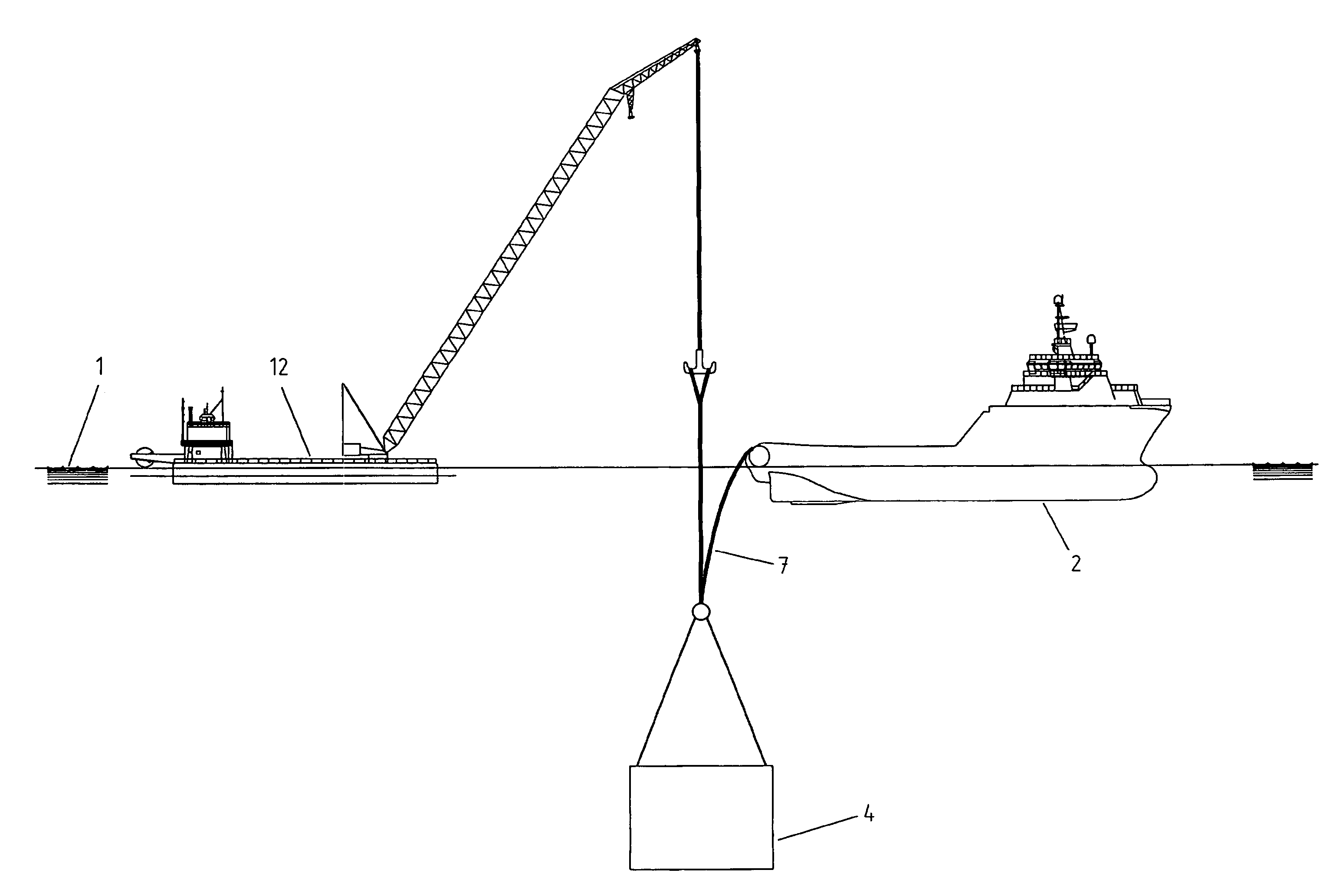
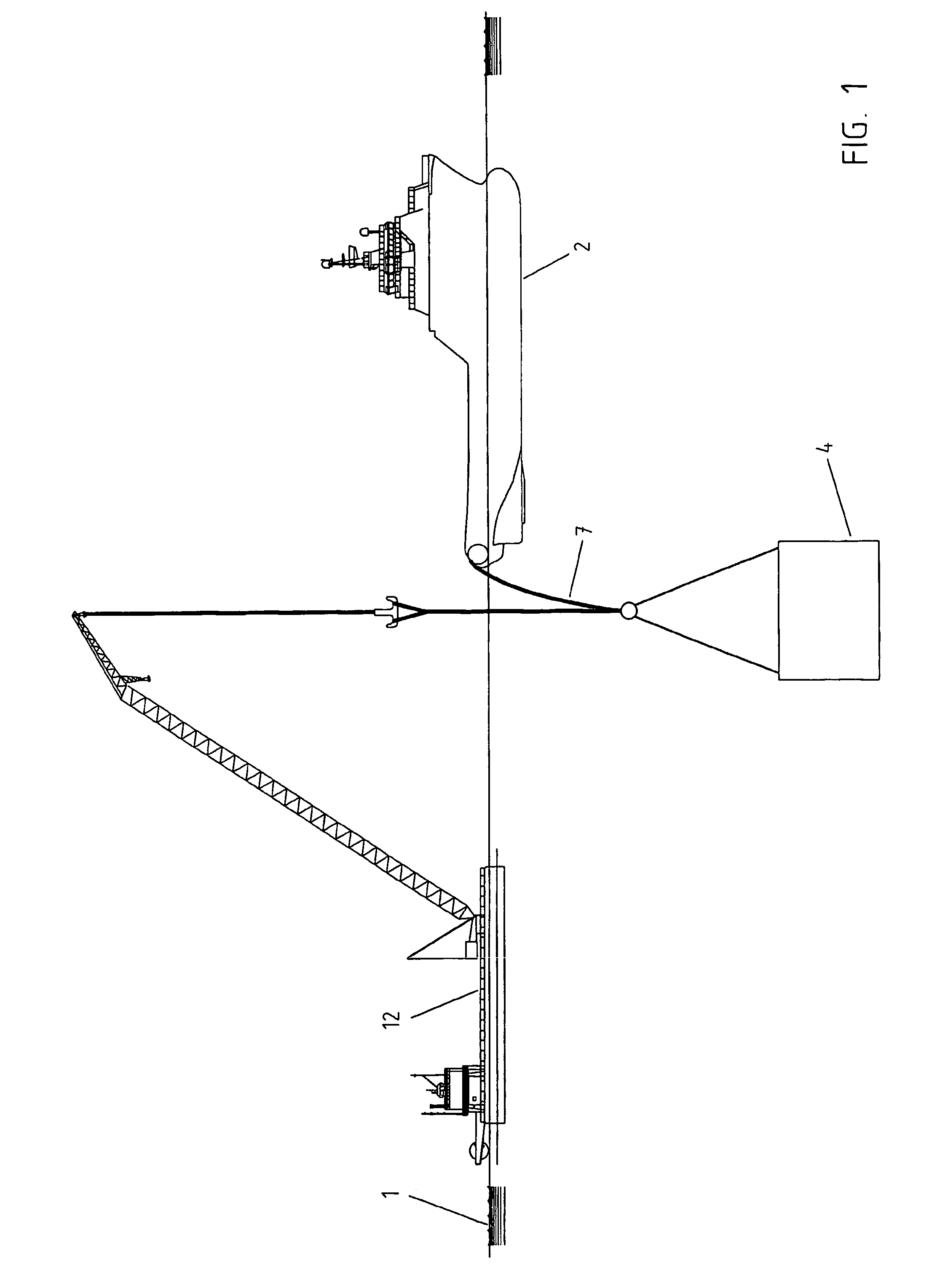
[0021]FIG. 1 shows the start of the operation according to the invention. The object 4 is being lifted through the surface 1 into the sea in sheltered waters after having been lifted off the deck of a vessel or transportation barge by a crane vessel 12. The object will be connected to the lower part of the suspension arrangement 7 and hung off in shark jaws at the stern of the towing vessel 2. The lifting wire from the crane vessel is then disconnected from the object.

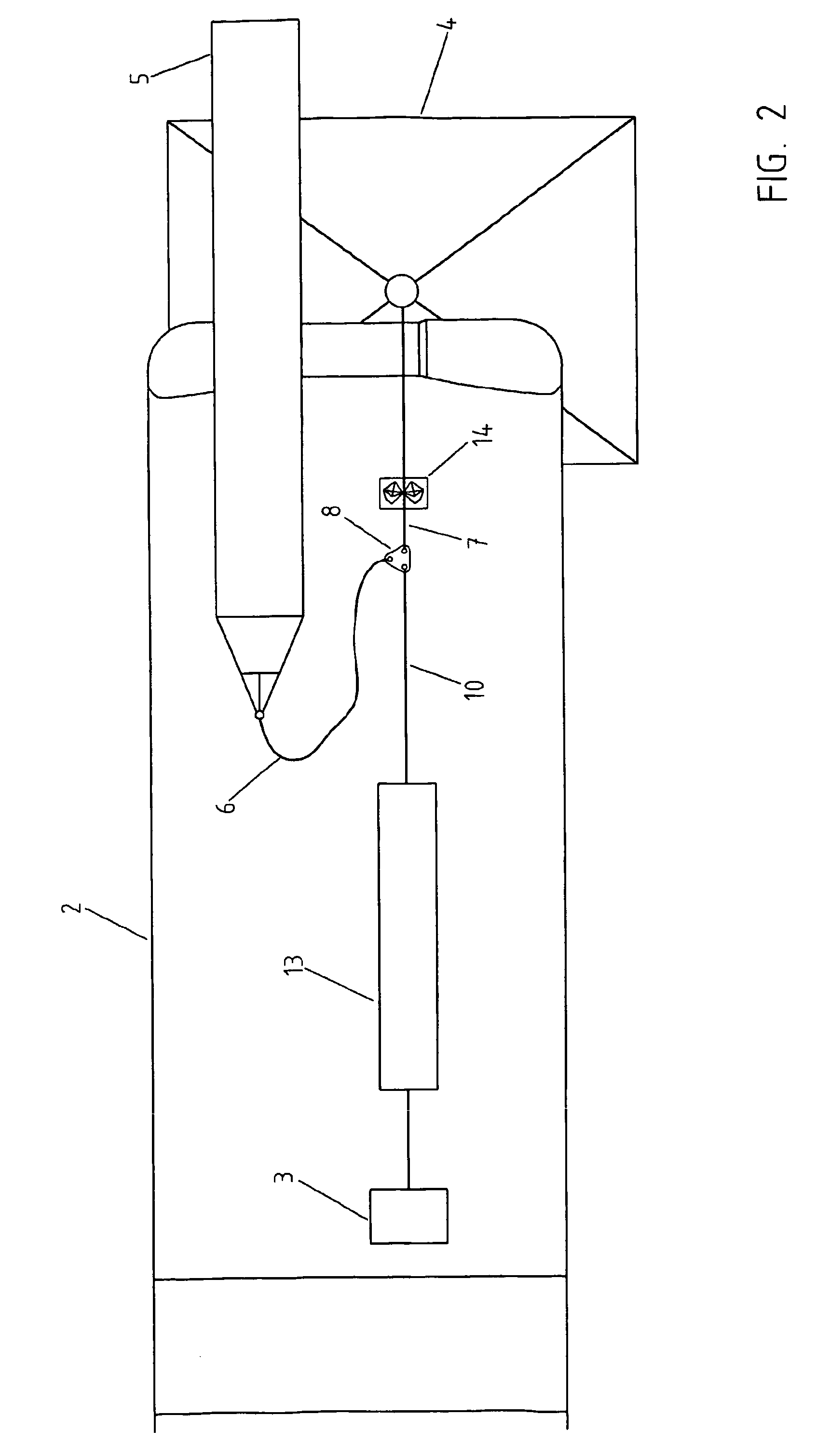
[0022]FIG. 2 shows the object 4 hanging just beneath the stern of the towing vessel 2, hung off in the shark jaws 14. The buoyancy unit 5 is lying on deck of the vessel and is connected to the tri-plate 8. The towing winch wire 10, running from the towing winch 3 via a heave compensator 13 on deck, is also connected to the tri-plate.

[0023]FIGS. 3A–F show the launch of the buoyancy unit 5 from the towing vessel 2 and the subsequent object 4 weight transfer from the towing winch 3 to the buoyancy unit. In FIGS. 3A–C the ...


PUM


Abstract

Method for transport and installation of objects at sea, particularly relating to transport and installation of obs jects that are part of the infrastructure in oil and gas fields offshore, the object (4) is put in the sea at a suitable location near the shore or in sheltered waters, then towed to the installation site while being suspended in a slender buoyancy unit (5) acting much like a heave compensating unit. Upon arrival at the installation site, the suspension of the object (4) is transferred from the buoyancy unit (5) to a heave compensated winch (3) on a surface vessel (2), preferably the same vessel as used for the preceding towing operation. The winch is used to lower is the object (4) to its destination on the sea bottom or a predetermined location above the sea bottom.

Description

RELATED APPLICATIONS[0001]The present application is a National Phase application of PCT / N003 / 00078 filed on Mar. 6, 2003 and publish in English, which claims priority from Norwegian Patent Application No. 20021119 filed on Mar. 6, 2002, the disclosure of which is incorporated herein by reference.FIELD OF THE INVENTION[0002]Oil and gas field developments are experiencing a push towards underwater production with more of the infrastructure placed on the seabed. There is thus an increasing need for transportation of objects with subsequent installation of the objects at the field. Also, with an increasing number of oil and gas fields being decommissioned, there is a growing need for removal of objects with subsequent transport to shore. Some of the objects that are to be installed or removed from the offshore sites are relatively complicated with large dimensions and weights. One is often dependent on costly vessels and equipment, and the availability of such vessels may also be poor....

Claims


Application Information

Patent Timeline
Patent Type & Authority Patents(United States)
IPC IPC(8): E02B17/00B63B35/00B63B9/06B63B21/66B63B22/00B63B27/08B63C7/02E21B19/00
CPCB63B21/66B63B22/00E21B19/002B63B35/003B63C7/02B63B27/08B63B9/065E02B2017/0052B63B27/36E02D23/08B63B77/00
Inventor TANGEN, GUNNARHVAM, LARS
Owner AKER MARINE CONTRACTORS
Why Eureka
Try Eureka