Dialysis catheter

Inactive Publication Date: 2006-03-14
ARGON MEDICAL DEVICES
View PDF161 Cites 185 Cited by
  • Summary
  • Abstract
  • Description
  • Claims
  • Application Information

AI Technical Summary

Benefits of technology

[0032]The present invention provides, in one aspect a catheter for delivering and withdrawing blood from a patient's body comprising a catheter body having a central return lumen extending from a proximal portion of the catheter body to the distal portion to allow blood passage there

Problems solved by technology

This multiple step process of inserting the Medcomp dialysis catheter is time consuming and complicates the surgical procedure.
These multiple steps add to the cost of the procedure, not only because of the additional surgeon's time but because additional components, such as the tear-away sheath, are required which increases the overall cost of the catheter system.
Also, removal of the dilator increases the tendency of the sheath to kink causing difficulties in catheter insertion.
The use of the tear away sheath is also potentially problematic.
However, the sheath can potentially cause damage to the vessel wall as it is being pulled apart and can cause infection.
Moreover, pulling the sheath laterally can enlarge the incision, thereby increasing the difficulty of closing the incision at the end of the procedure.
The edges of the tear away can also lacerate the surgeon's glove and finger.
Over dilation by the sheath can also cause blood leakage.
An additional potential risk with utilizing tear away sheaths is that air embolism can occur.
If the patient inhales during this catheter exchange, an air bubble can enter t

Method used


Image

  • Dialysis catheter
  • Dialysis catheter
  • Dialysis catheter

Examples


first embodiment

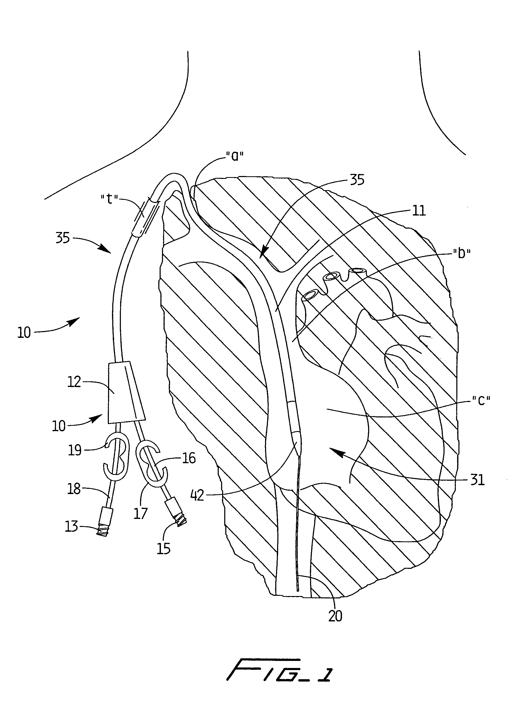
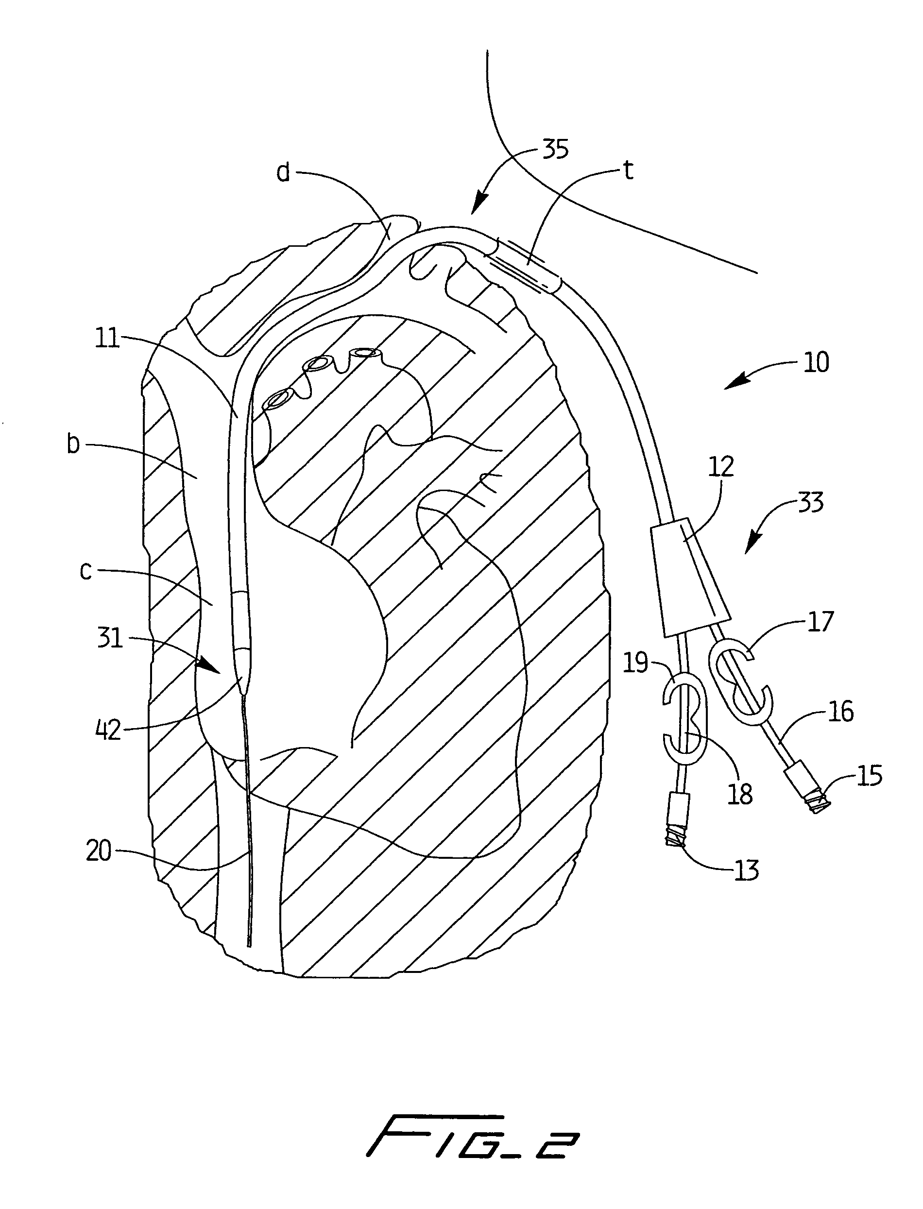
[0121]Referring now in detail to the drawings where like reference numerals identify similar or like components throughout the several views, the catheter of the present invention is designated generally by reference numeral 10. The catheter 10 is typically inserted into an area of high velocity blood flow to ensure sufficient blood can be transported from the body for dialysis. FIG. 1 illustrates the catheter 10 inserted through the right internal jugular vein “a”, into the superior vena cava “b”, and into the right atrium “c”; FIG. 2 illustrates the catheter 10 inserted into the left internal jugular vein “d”, into the superior vena cava “b” and into the right atrium “c”. Insertion into the right atrium, from either the right or left side provides the necessary high blood flow to the dialysis machine. Note that the catheter body (catheter tube) 11 is sufficiently flexible to enable it to bend to accommodate the anatomical curves as shown.

[0122]Catheter 10 has a catheter body or ca...

third embodiment

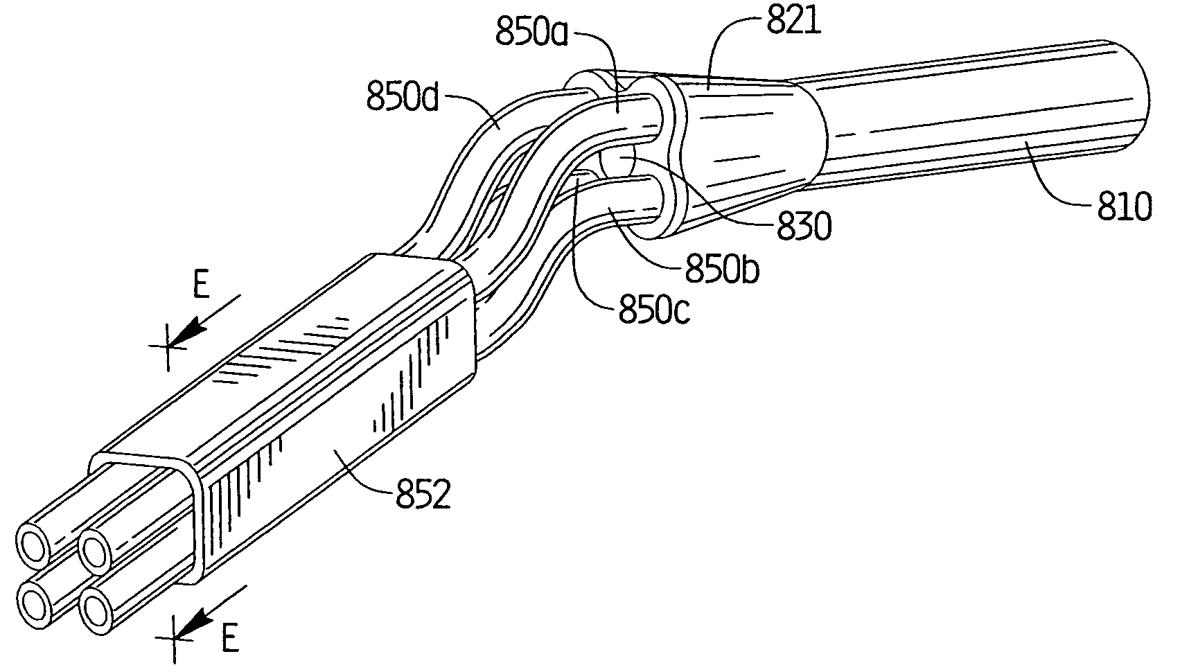
[0136]To facilitate insertion, the catheter is configured to receive a stiffening member in the form of a stiffening rod which stretches the catheter to reduce its profile to aid in over the wire insertion and better navigate through small vessels. That is, the stiffening rod is inserted into central lumen 40 of catheter 10 and torqued to stiffen the flexible catheter for ease in over the wire insertion and navigation through the small vessels, and to reduce the outer diameter of the catheter body by stretching it during insertion. After placement of the catheter 10, the stiffening rod is removed, allowing the catheter to return to its higher profile position with the lumens of the necessary size for blood transport to and from the body. Two embodiments of the stiffening rods are illustrated in FIGS. 4A and 4B and are shown prior to insertion into the catheter 10 in FIG. 3. the stiffening rod is illustrated in FIG. 49.

[0137]Turning to the first embodiment of the stiffening rod illus...


PUM


Abstract

A catheter for delivering and withdrawing blood from a patient's body comprising a catheter body having a distal portion, a central return lumen extending from a proximal portion of the catheter body to the distal portion to allow blood passage therethrough, at least three longitudinally extending intake lumens independent of the return lumen and radially displaced with respect to the return lumen, and means for enabling simultaneous cut off of fluid flow to the at least three longitudinally extending lumens.

Description

[0001]This application is a continuation-in part of application Ser. No. 10 / 025,506, filed Dec. 19, 2001, now U.S. Pat. No. 6,814,718 issued Nov. 9, 2004 which claims priority from provisional patent application Ser. No. 60 / 260,592, filed Jan. 9, 2001. The entire contents of these applications are incorporated herein by reference.BACKGROUND[0002]1. Technical Field[0003]This application relates to a catheter and more particularly to a multi-lumen catheter which facilitates hemodialysis.[0004]2. Background of Related Art[0005]Hemodialysis is a well known method of providing renal (kidney) function by circulating blood. The kidneys are organs which function to extract water and urea, mineral salts, toxins, and other waste products from the blood with filtering units called nephrons. From the nephrons the collected waste is sent to the bladder for excretion. For patients having one or both defective kidneys, the hemodialysis procedure is life saving because it provides a machine to simu...

Claims


Application Information

Patent Timeline
IPC IPC(8): A61M1/00A61M25/00A61M5/00A61M1/28A61M25/04
CPCA61M1/285A61M1/3661A61M25/0028A61M25/007A61M25/0071A61M25/008A61M25/0097A61M25/04A61M25/0668A61M25/09041A61M25/0029A61M25/0032A61M25/0068A61M2025/0006A61M2025/0031A61M2025/0034A61M2025/0036A61M2025/0081A61M2025/0286A61M2025/09125A61M25/001
Inventor MCGUCKIN, JR., JAMES F.PARIS, MICHAEL W.TASHJIAN, PAULHINCHLIFFE, PETER W. J.
Owner ARGON MEDICAL DEVICES
Why Eureka
Try Eureka