Rotational thermophoretic drying

a thermophoretic drying and rotational technology, applied in the direction of cleaning processes and equipment, cleaning using liquids, lighting and heating equipment, etc., can solve the problems of malfunctioning devices, inability to use both methods, and inability to work well for both methods, so as to reduce watermarking

Inactive Publication Date: 2006-03-14
APPLIED MATERIALS INC
View PDF5 Cites 6 Cited by
  • Summary
  • Abstract
  • Description
  • Claims
  • Application Information

AI Technical Summary

Benefits of technology

[0009]During a wafer cleaning process, cleaning and rinse solutions may be applied to one or both sides of the wafer positioned in a rotatable platter. Wafer drying can be required, such as, for example, after a final (last) hydrofluoric acid (HF) etch cycle. After the HF-Last etch, the rotational thermophoretic drying of the patterned or blanket hydrophobic wafer top surface can be performed and, as a result, the wafer top surface can have reduced watermarking or be watermark-free.

Problems solved by technology

“HF-Last” (a last hydrofluoric acid etch) processing poses distinct problems to the process engineer such as how to produce a particle-free hydrophobic bare silicon wafer at sub-0.10 micron line widths, while also being able to produce a completely watermark-free “mix-surface” patterned wafer.
While one process may work well for one, it may not work well for both.
Watermarks are among the most common contamination problems found in LSI wet processing today, principally attributed to post HF rinsing and drying processes where both hydrophobic and hydrophilic surface states exist on the wafer.
However, this method is not possible when the wafers have any topography (patterns) that can be damaged by the brushes.
Contamination left on the device side can cause a malfunctioning device.
Contamination left on the non-device side (backside) can cause a number of problems.
Backside contamination can cause the photolithography step on the front side to be out of focus.
Contamination on the backside can cause contamination of the processing tools, which in turn can be transferred to the front side of the wafer.
Finally, metallic contamination on the backside, when deposited before a high temperature operation, can diffuse through the silicon wafer and end up on the device side of the wafer causing a malfunctioning of the device.

Method used


Image

  • Rotational thermophoretic drying
  • Rotational thermophoretic drying
  • Rotational thermophoretic drying

Examples


Embodiment Construction

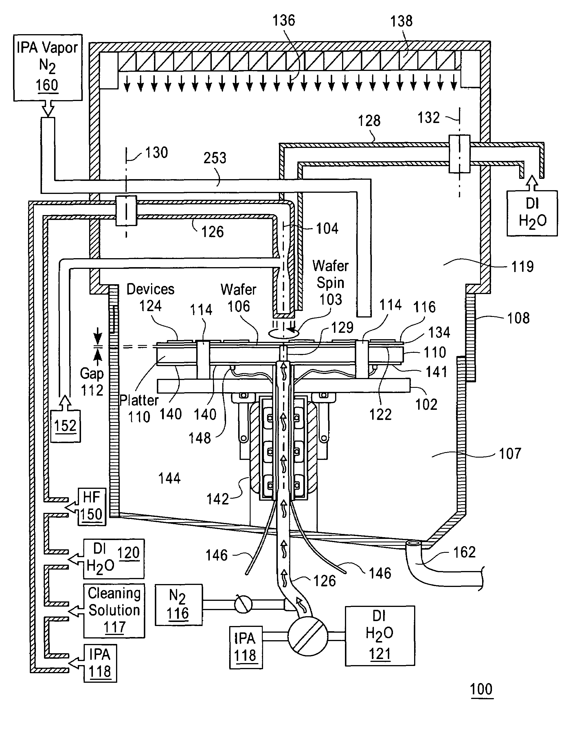
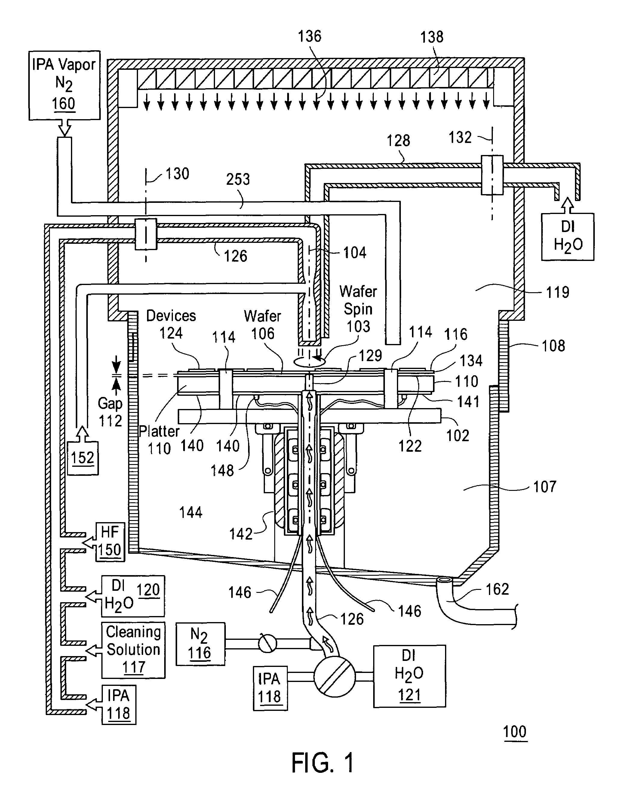
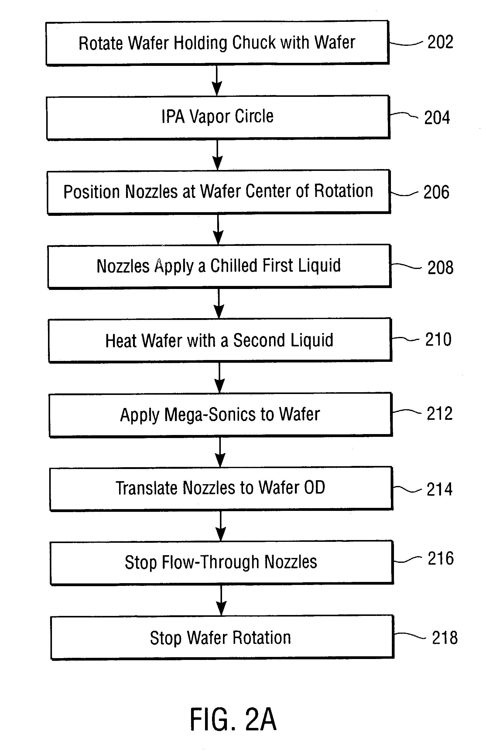
[0014]A method to provide rotational thermophoretic drying of a wafer within a single wafer cleaning chamber is disclosed. The method to use rotational thermophoretic forces in a wafer dry cycle can remove particles on the wafer surface, such as, for example, to provide watermark-free rotational drying of patterned or blanket hydrophobic semiconductor wafers.

[0015]During wafer cleaning, a cleaning or rinse solution can be applied to one or both sides of a wafer positioned in a rotatable platter. The cleaning process, such as an RCA-type cleaning process, can be applied to the wafer and after which, a final (last) hydrofluoric acid (HF) etch can be accomplished. A rotational thermophoretic drying process can then be performed.

[0016]Thermophoretic forces can be exerted on particles through the generation of a temperature gradient. The thermal gradient can cause the repulsion of small colloidal sized particulates, suspended in a surrounding (cooler) liquid layer, away from a (hotter) w...


PUM

PropertyMeasurementUnit
thicknessaaaaaaaaaa
frequenciesaaaaaaaaaa

Abstract

A method that includes rotating a wafer, heating the wafer, applying a first liquid through one or more nozzles to a center of a topside of the wafer that is cooler than the heated wafer, and translating the one or more nozzles to an outer diameter edge of the wafer.

Description

BACKGROUND OF THE INVENTION[0001]1. Field of the Invention[0002]The present invention relates to the field of cleaning of a substrate surface and more particularly to the area of chemical cleaning of a semiconductor wafer.[0003]2. Discussion of Related Art[0004]In semiconductor wafer substrate (wafer) cleaning, particle removal is essential. Particles can be removed by chemical means or by mechanical means. In current state of the art, particles are usually removed by both a combination of mechanical means and chemical means. “HF-Last” (a last hydrofluoric acid etch) processing poses distinct problems to the process engineer such as how to produce a particle-free hydrophobic bare silicon wafer at sub-0.10 micron line widths, while also being able to produce a completely watermark-free “mix-surface” patterned wafer. The mixed surface identifies both hydrophilic oxides as well as hydrophobic bare silicon on the same wafer. While one process may work well for one, it may not work well ...

Claims


Application Information

Patent Timeline
Patent Type & Authority Patents(United States)
IPC IPC(8): B08B7/04B08B3/02H01L21/00
CPCH01L21/67028H01L21/67051H01L21/67034
Inventor VERHAVERBEKE, STEVEN
Owner APPLIED MATERIALS INC
Why Eureka
Try Eureka