
Solid polymer electrolyte membrane, solid polymer electrolyte fuel cell using the membrane and method of fabricating the same

a technology electrolyte, which is applied in the direction of non-aqueous electrolytes, conductive materials, chemical/physical processes, etc., can solve the problems of unfavorable structural strength of membrane, and poor assembly of solid polymer electrolyte membrane and catalytic layer, etc., to achieve the effect of improving the ease of handling

Inactive Publication Date: 2006-03-14
SANYO ELECTRIC CO LTD
View PDF11 Cites 16 Cited by
  • Summary
  • Abstract
  • Description
  • Claims
  • Application Information

AI Technical Summary

Benefits of technology

[0017]In view of the circumstance described above, an object of the present invention is to provide a solid polymer electrolyte fuel cell and a method of fabricating the same, in which no thermal damage is caused to the solid polymer electrolyte membrane and the solid polymer electrolyte material, and in which the membrane and the catalyst layer are assembled properly, even when the solid polymer electrolyte membrane and the catalytic layer are formed of different solid polymer electrolyte materials. Another object of the present invention is to provide a solid polymer electrolyte fuel cell comprising a solid polymer electrolyte membrane with high heat endurance and a method of fabricating the same. Still another object of the present invention is to provide a low-cost solid polymer electrolyte fuel cell and a method of fabricating the same. Yet another object of the present invention is to provide a solid polymer electrolyte membrane used in the solid polymer electrolyte fuel cell as described above.
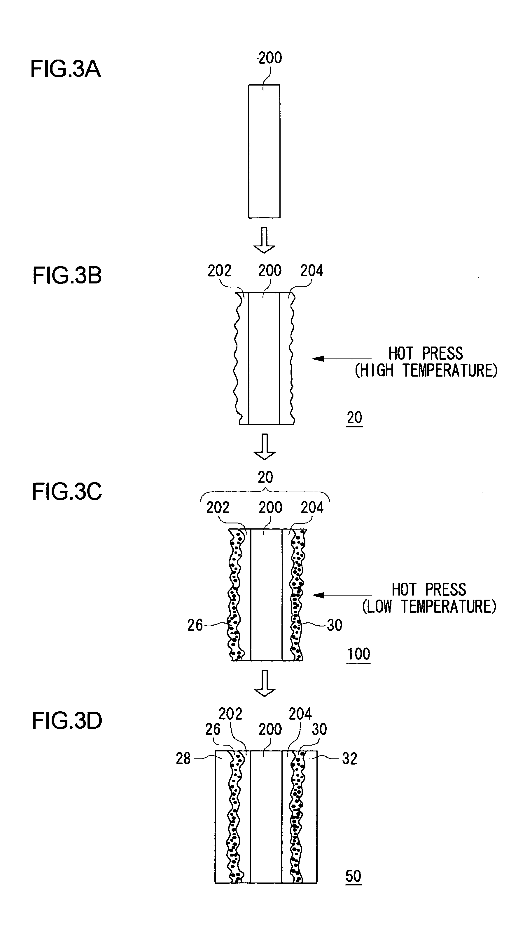
[0055]In this way, heating and applying of pressure (hot press) are performed at a temperature appropriate for the material so that the solid polymer electrolyte membrane and the catalyst layer are assembled properly without applying thermal damage to the materials.

Problems solved by technology

Using the non-fluorinated polymer of the sulfonic acid type to form a solid polymer electrolyte membrane, however, presents a problem in that strength of assembly of the membrane and the heterologous solid polymer electrolyte material included in the catalytic layer is unfavorable.
Use of a heterologous material causes an assembly of the solid polymer electrolyte membrane and a catalytic layer to be become poor.
A solid polymer electrolyte material formed of fluorinated polymer differs from a solid polymer electrolyte material of non-fluorinated polymer in glass transformation temperature and melting temperature so that sufficiently strong assembly is difficult.
For example, when the glass transformation temperature and melting temperature of a solid polymer electrolyte material of non-fluorinated polymer are higher than those of a solid polymer electrolyte material of fluorinated polymer, and when the materials are assembled in a hot press process at a relatively low temperature, an interface with the catalyst and the solid polymer electrolyte material of fluorinated polymer in the porous catalytic layer cannot be established, because the solid polymer electrolyte material of non-fluorinated polymer exhibits poor fluidity.
When a solid polymer electrolyte membrane formed of a solid polymer electrolyte material of non-fluorinated polymer characterized by a high glass transformation temperature and melting temperature is bonded to an electrode that includes a polymer electrolyte material of fluorinated polymer characterized by a low glass transformation temperature and melting temperature, to form an assembly, the surface of the catalytic layer may not be flat, and the quantity of the polymer electrolyte material in the catalytic layer is limited.
In these cases, the aforementioned problem is more serious.
When the solid polymer electrolyte membrane and the catalytic layer are not assembled properly, conduction of hydrogen ions to the triphasic interface becomes insufficient so that the performance of the fuel cell drops.
When the materials are assembled in a hot press process at a relatively high temperature, conductivity of hydrogen ions is lost due to, for example, the clustering structure of the solid polymer electrolyte material of fluorinated polymer being destroyed, causing a drop in the performance of the fuel cell.
A problem with this technique is that the solid polymer electrolyte material is excessively so abundant in the catalytic layer that the cell performance drops as a result of gas diffusion being prevented.

Method used


Image

  • Solid polymer electrolyte membrane, solid polymer electrolyte fuel cell using the membrane and method of fabricating the same
  • Solid polymer electrolyte membrane, solid polymer electrolyte fuel cell using the membrane and method of fabricating the same
  • Solid polymer electrolyte membrane, solid polymer electrolyte fuel cell using the membrane and method of fabricating the same

Examples


first embodiment

(First Embodiment)

[0069]A description will now be given of a construction of a solid polymer electrolyte fuel cell according to the embodiments of the present invention.

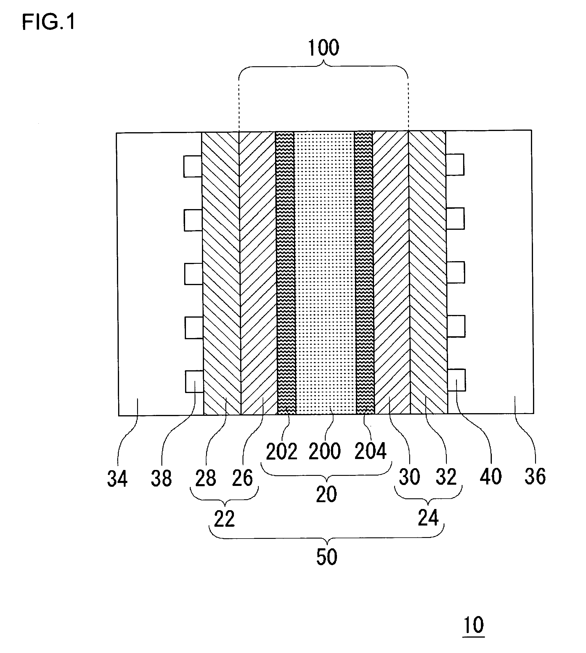
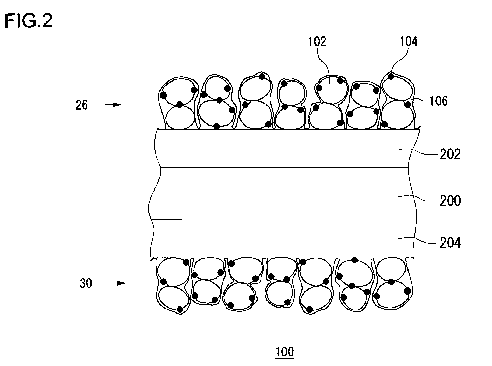
[0070]FIG. 1 schematically shows a cross section of a fuel cell 10 according to the embodiments of the present invention. The fuel cell 10 is provided with a sheet cell 50, and a separator 34 and a separator 36 are provided on respective sides of the cell 50. In this example, only one cell 50 is shown. Alternatively, a laminate of a plurality of cells 50 sandwiching the separator 34 and the separator 36 may be provided to construct the fuel cell 10. The cell 50 has a solid polymer electrolyte membrane 20, a fuel electrode 22 and an air electrode 24. The fuel electrode 22 has a laminate of a catalytic layer 26 and a gas diffusion layer 28, and the air electrode 24 similarly has a laminate of a catalytic layer 30 and a gas diffusion layer 32. The catalytic layer 26 of the fuel electrode 22 and the catalytic layer 30 of...

second embodiment

(Second Embodiment)

[0112]In this embodiment, the method of fabricating the electrolyte membrane 100 fitted with catalyst is different from that of the first embodiment. In this embodiment, the fuel cell 10 has a construction similar to that of the first embodiment described by referring to FIGS. 1 and 2. In this and the first embodiment, like components are denoted by like reference symbols and the description thereof is omitted where appropriate.

[0113]FIG. 5 shows a process of fabricating the electrolyte membrane 100 fitted with catalyst according to this embodiment. In a similar configuration as the first embodiment, catalyst ink and fluid dispersion are produced according to this embodiment.

[0114]First, the first solid polymer electrolyte membrane 200 is prepared (FIG. 5(a)). Following this, fluid dispersion is applied to both sides of the first solid polymer electrolyte membrane 200 by brush application, spray application, screen printing, etc. Alternatively, the first solid pol...

third embodiment

(Third Embodiment)

[0120]In this embodiment, the method of fabricating the electrolyte membrane 100 fitted with catalyst is different from that of the first and second embodiments. In this embodiment, the fuel cell 10 has a construction similar to that of the first embodiment described by referring to FIGS. 1 and 2. In this and the first embodiment, like components are denoted by like reference symbols and the description are omitted where appropriate.

[0121]FIG. 7 shows a process of fabricating the electrolyte membrane 100 fitted with catalyst according to this embodiment. In a similar configuration as the first embodiment, fluid dispersion is produced.

[0122]First, the first solid polymer electrolyte membrane 200 is prepared (FIG. 7(a)). Following this, the fluid dispersion is applied to both sides of the first solid polymer electrolyte membrane 200 by brush application, spray application, screen printing, etc, so as to form the second solid polymer electrolyte membranes 202 and 204 ...


PUM

PropertyMeasurementUnit
temperatureaaaaaaaaaa
thicknessaaaaaaaaaa
thicknessaaaaaaaaaa

Abstract

A solid polymer electrolyte membrane and a catalytic layer are properly assembled even when the solid polymer electrolyte membrane and an ion exchange resin in the catalytic layer are formed of different materials. In a fuel cell, a solid polymer electrolyte membrane 20 is provided with a first solid polymer electrolyte membrane 200, and second solid polymer electrolyte membranes 202 and 204 provided at respective sides thereof. The second solid polymer electrolyte membranes 202 and 204 are formed of the same material as the ion exchange resin (not shown) included in a catalytic layer 26 and a catalytic layer 30.

Description

[0001]This is a continuation of International Application PCT / JP03 / 15414, filed Dec. 2, 2003.TECHNICAL FIELD[0002]The present invention relates to a solid polymer electrolyte membranes, a fuel cell using the membrane and a method of fabricating the same.BACKGROUND TECHNOLOGY[0003]In recent years, attention is paid to fuel cells characterized by high energy conversion efficiency and not producing hazardous materials as a result of generating electricity. A solid polymer electrolyte fuel cell operating at a temperature of 100° C. or lower is known as one type of such fuel cells.[0004]A solid polymer electrolyte fuel cell is a power generating device that has a basic structure in which a solid polymer electrolyte membrane is sandwiched between a fuel electrode and an air electrode. Hydrogen is supplied to the fuel electrode and oxygen is supplied to the air electrode. A solid polymer electrolyte fuel cell generates electricity according to the following electrochemical reaction.Fuel el...

Claims


Application Information

Patent Timeline
Patent Type & Authority Patents(United States)
IPC IPC(8): H01M8/10H01B1/12
CPCH01B1/122H01M8/1004H01M8/1023H01M8/1032H01M8/1039H01M8/1053Y10T29/49114H01M2300/0094Y02E60/523Y10T29/49108Y10T29/49112Y10T29/49115Y10T29/53135H01M2300/0082Y02E60/50H01M8/10
Inventor SAKAMOTO, SHIGERUSANDA, HIROKONAGANO, HIROSAKUKUROMATSU, HIDEKAZUNAMURA, KIYOYUKI
Owner SANYO ELECTRIC CO LTD
Learn More