Electronic label

a technology of electronic labels and labels, applied in the direction of identification means, instruments, burglar alarm mechanical actuation, etc., can solve the problems of major drawbacks of distance constraints, and the inability of semiconductor sheets to read at any time, so as to increase the acceptable reading distance

Inactive Publication Date: 2006-03-14
NAGRAVISION SA
View PDF9 Cites 13 Cited by
  • Summary
  • Abstract
  • Description
  • Claims
  • Application Information

AI Technical Summary

Benefits of technology

[0019]According to another embodiment, the sheet exceeds slightly the surface of the coil, creating an edge

Problems solved by technology

Nevertheless, the problem that this kind of using comes from the nature of the object.
In certain applications, one easily imagines that this distance constraint can present major drawbacks for objects having an

Method used


Image

  • Electronic label
  • Electronic label

Examples


Embodiment Construction

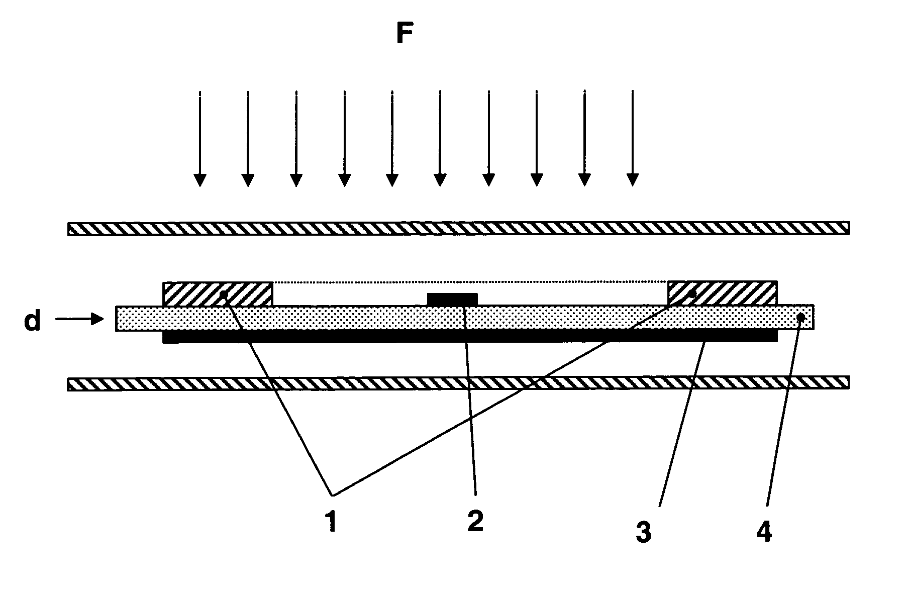
[0026]In FIG. 1, representing a section of an electronic label, one can distinguish the schematized coil 1 as well as the electronic chip 2. Note that although this chip is situated inside the coil, it also can be situated outside the surface defined by the coil.

[0027]Under the coil 1, is placed the magneto reflective sheet 3 separated by an insulating layer 4 and defining the distance between the coil and the magnetic sheet. The presence of this insulating layer is not necessary to obtain the desired effect; the magneto reflective sheet can be directly applied onto the coil.

[0028]This sheet 3 is placed on the opposite side of the reader (schematized by field lines F), that is to say on the application side of the label on the object having metallic characteristics.

[0029]This set can be embedded in a resin or encapsulated between two protection sheets. The shape of this label can be any as a card, a button, or mounted on a flexible support.

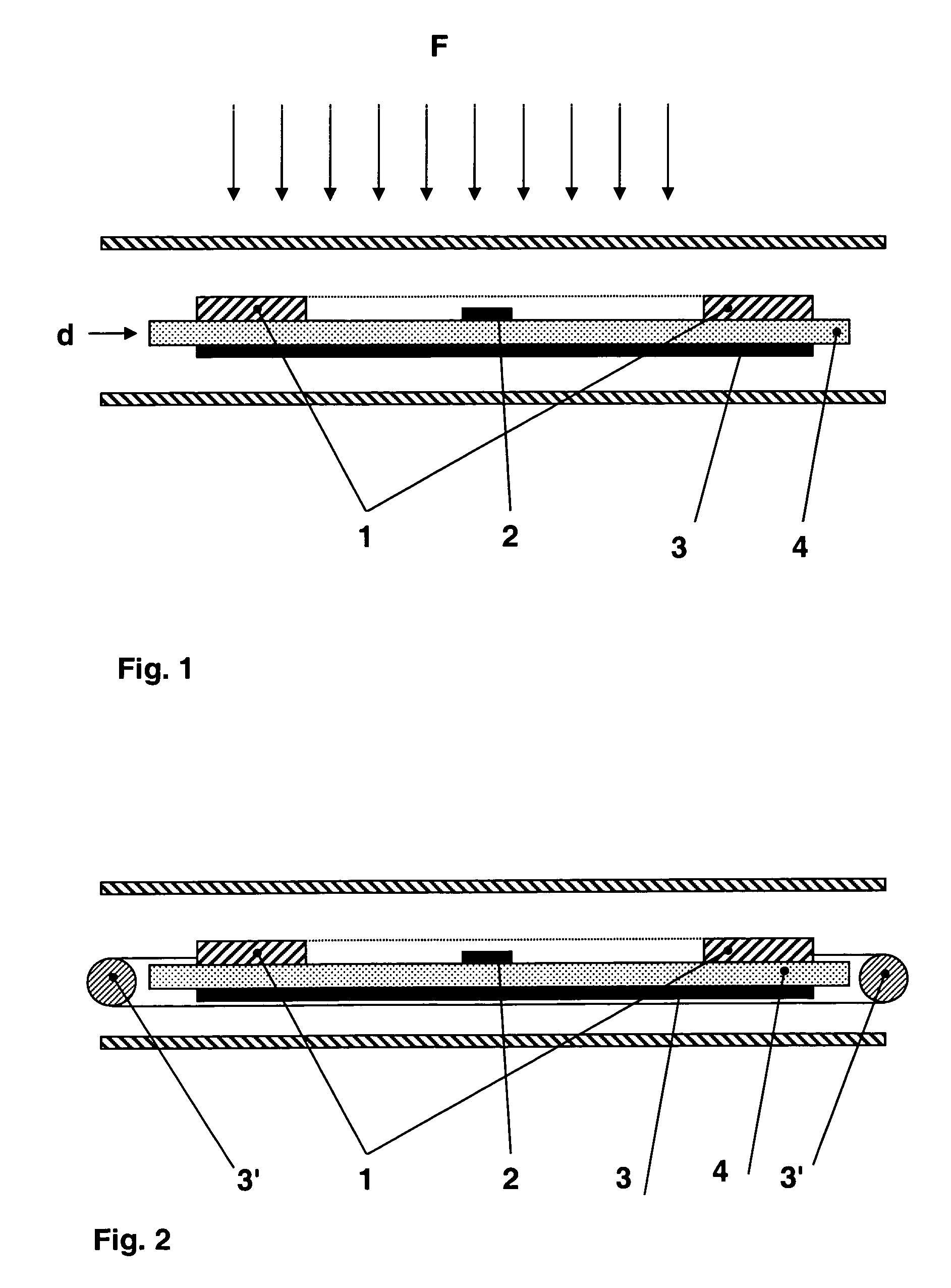
[0030]According to a variant of the inventi...


PUM


Abstract

One characteristic of electronic labels is that they can be read and written on without electrical contact through the communication coil (1). The reading heading is then positioned at some distance and communicates with the label through electromagnetic waves. When these labels are placed on metallic objects, reading becomes difficult even impossible because of the dispersion of the waves in the object. To overcome this drawback, the invention proposes the adding of an electromagnetic conductive element (3, 3′) to the coil (1) in order to insulate it (1) and enhance the reception quality.

Description

FIELD OF THE INVENTION[0001]This invention concerns the domain of electronic labels, more particularly labels designed to be placed on a metallic object.BACKGROUND OF THE INVENTION[0002]By electronic label one understands, a set having at least one support, an antenna and an electronic chip. This set can include several antennas or several chips according to the requirements. One finds them in the form of a button, in chip cards and even in luggage labels. Thanks to their antennas, they can communicate with a remote reader. The antenna serves not only as a means of communication, but also to produce the necessary energy to feed the electronic chip.[0003]Some of these labels do not include electronic chips but passive components such as resistors or fuses. They are used to identify objects, for example in an anti-theft application.[0004]According to the embodiments, the antenna is fitted to the flexible support or directly engraved or cut on this same support.[0005]There are a lot of...

Claims


Application Information

Patent Timeline
IPC IPC(8): G08B13/14G06K19/07G06K19/077G09F3/00
CPCG06K19/07771G06K19/07749G06K19/077
Inventor DROZ, FRANCOIS
Owner NAGRAVISION SA
Why Eureka
Try Eureka