Frequency conversion circuit using common local synthesizer

a technology of local synthesizer and frequency conversion circuit, which is applied in the direction of transmission, electrically long antennas, antennas, etc., can solve the problems of large filter size, high cost, and difficult design of solid state circuits

Inactive Publication Date: 2006-03-14
GOOGLE LLC
View PDF10 Cites 15 Cited by
  • Summary
  • Abstract
  • Description
  • Claims
  • Application Information

AI Technical Summary

Benefits of technology

[0009]The present invention is a radio for use in microwave data link applications in which a common local oscillator signal is used for both a final up-converter stage and an initial down-converter stage. The frequency of the common local oscillator is also chosen to correspond to an integer multiple of a needed local oscillator frequency for an earlier up-converter stage or a later down-converter stage. The required carrier frequency ...

Problems solved by technology

Depending upon the specific details of frequency allocations for upstream and downstream channels, the design of the solid state circuits can therefore present certain challenges.
This type of filter represents large size, high cost and, depending on the precise frequency band plan, its loss can become significant when very narrow bandwidths are required.
However, the high-Q, narrowband characteristic of the waveguide filter cannot be practically duplicated in other circuit technologies.
While a ...

Method used


Image

  • Frequency conversion circuit using common local synthesizer
  • Frequency conversion circuit using common local synthesizer
  • Frequency conversion circuit using common local synthesizer

Examples


Embodiment Construction

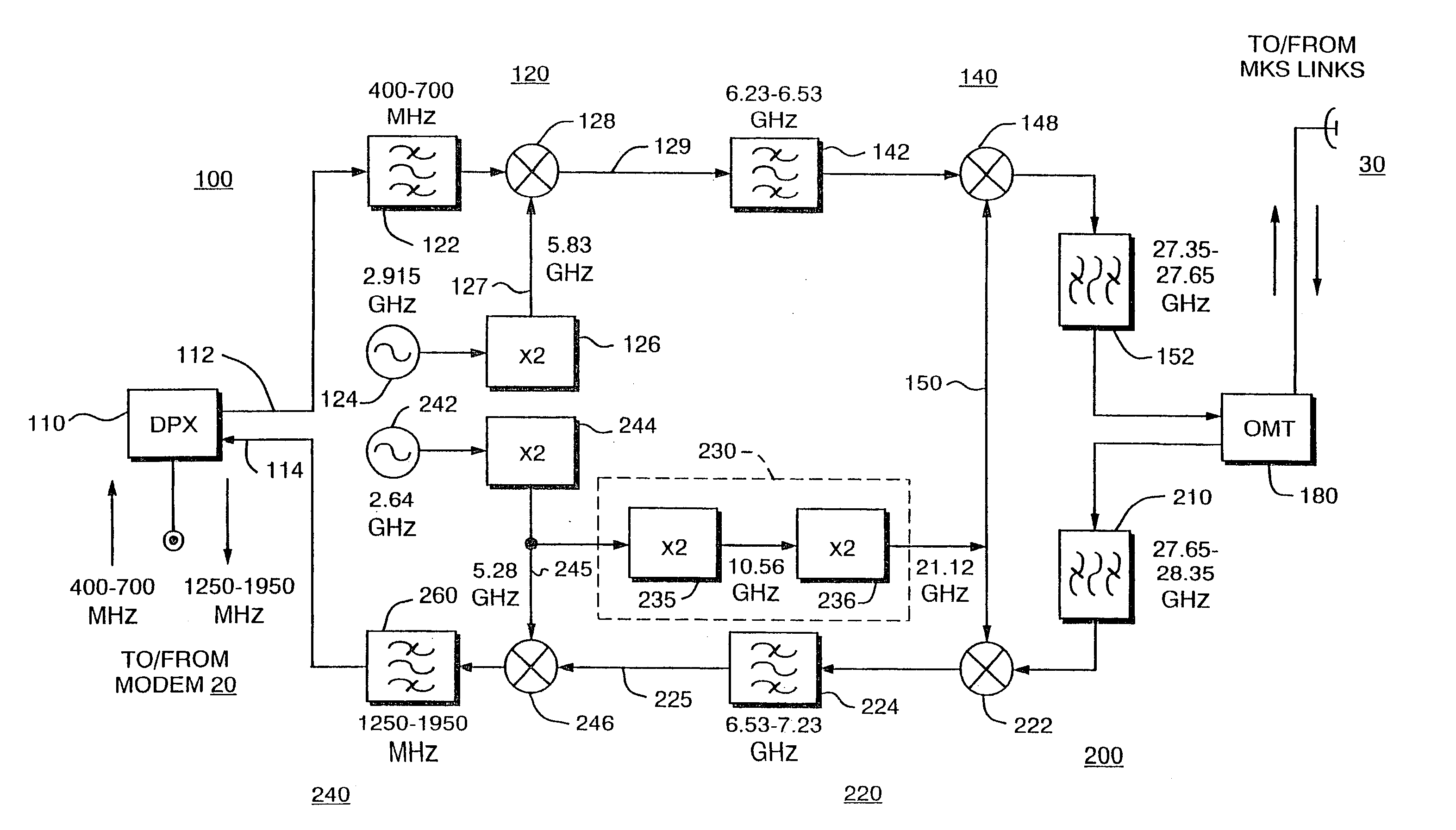
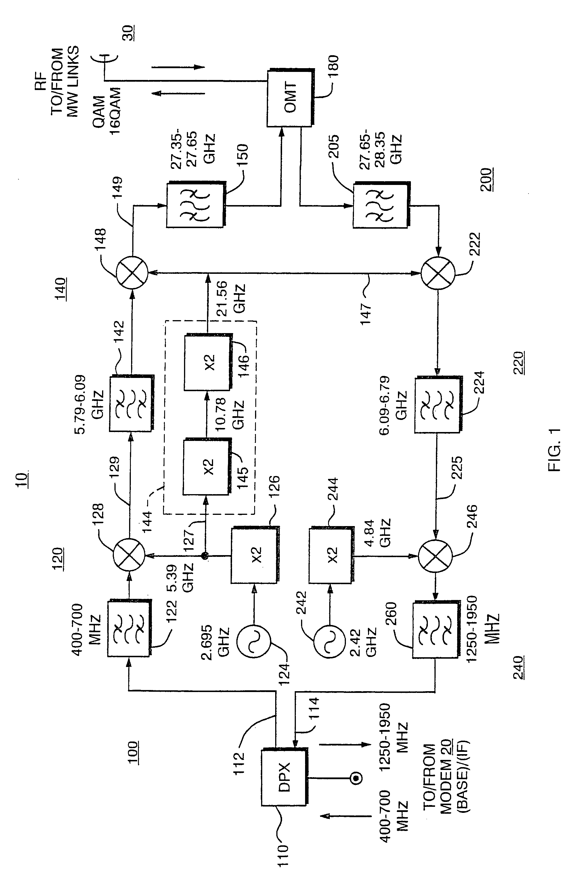
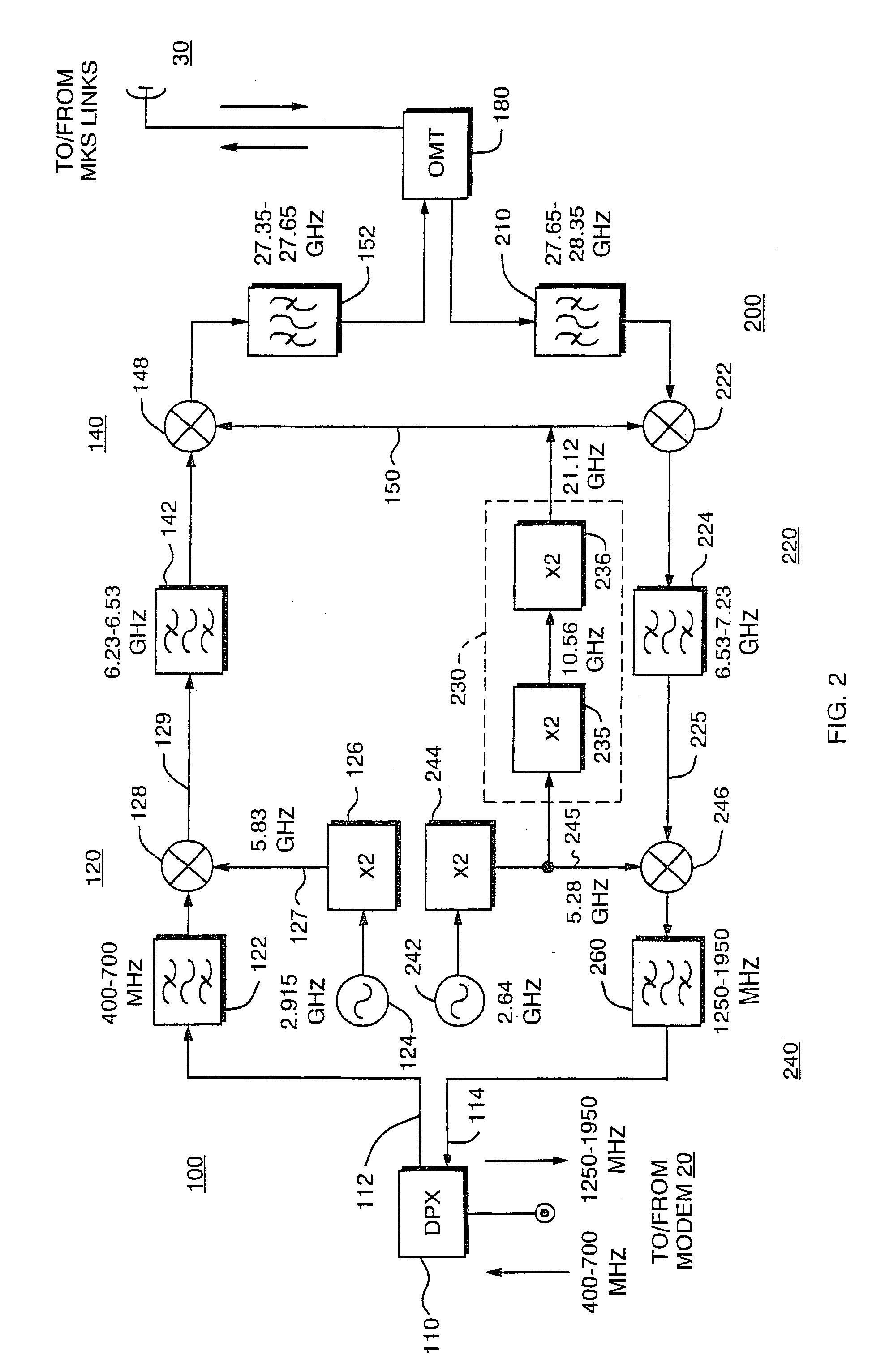
[0017]Turning attention now to FIG. 1, there is shown a radio transceiver 10 for coupling data signals between a modem 20 (not shown) and microwave frequency radio signals coupled to an antenna 30. The transceiver 10 includes a frequency converter having a transmit leg, or up-converter 100, and a receive leg, or down-converter 200. The up-converter 100 receives baseband or intermediate frequency (IF) signals from the modem 20 and provides radio frequency (RF) signals in a microwave frequency band to the antenna 30. The down-converter 200 receives microwave signals from the antenna 30 and provides them to the modem 20 in baseband or IF form.

[0018]The modem 20 may be of various types. In the illustrated embodiment, the modem 20 is a cable modem which provides digital Quadrature Amplitude Modulation (QAM) or 16-QAM signals in a 400–700 MHz intermediate frequency (IF) range in an upstream direction. The cable modem receives signals in a 1250–1950 MHz IF range in a down-link direction. H...


PUM


Abstract

A radio for use in microwave datalink applications in which a common local oscillator is used for both a final radio frequency (RF) up-converter stage and an initial RF down converter stage. The frequency of the common local oscillator corresponds to an integer multiple of a local oscillator needed for an earlier up-converter or later down converter stage. The circuit can be used to provide a radio frequency carrier in a 30 GHz band using Coaxial Resonator Oscillators (CRO's) that lend themselves to a planar microstrip circuit implementation.

Description

BACKGROUND OF THE INVENTION[0001]A number of access technologies are presently available for wireless data connectivity. These wireless access products include Wireless Local Loop (WLL), Fixed Wireless Access (FWA), Cellular Packet Data (CDPD), Wireless Local Area Network (WLAN), narrow aperture satellite technologies, Local Multipoint Distribution Service (LMDS), and Multipoint Distribution Service (MMDS). A range of data transfer speeds are supported with these technologies, including multiple or fractional T1 / E1 type, asynchronous transfer mode (ATM), digital video, plain old telephone service (POTS), and other types of digital signaling connections.[0002]Of chief interest to the present invention are broadband microwave communications systems, such as local multipoint distribution services (LMDS). Now available in the United States and in other countries, LMDS provides fast, flexible and economical broadband wireless connectivity, with line of sight coverage over a distance rang...

Claims


Application Information

Patent Timeline
IPC IPC(8): H04B1/26
CPCH04B1/403
Inventor KOH, CHRISTOPHER T.
Owner GOOGLE LLC
Why Eureka
Try Eureka