Method for forming an armature for an electric motor for a portable power tool

a portable power tool and electric motor technology, applied in the field of electric motors, can solve the problems of difficult to achieve consistent application process, large oven cost, difficult to perform reliable, consistent application process, etc., and achieve the effect of eliminating the difficulty in managing the application of trickle resin, reducing the cost of operation, and improving the resistance to extreme temperatures

Inactive Publication Date: 2006-03-21
BLACK & DECKER INC
View PDF287 Cites 24 Cited by
  • Summary
  • Abstract
  • Description
  • Claims
  • Application Information

AI Technical Summary

Benefits of technology

[0010]The present invention is directed to an armature for an electric motor which includes a thermally conductive coating applied over the magnet wires wound around the lamination stack thereof, to thereby form an excellent means for dissipating heat and holding the magnet wires stationary as well as holding the ends of the magnet wires secured to tangs on the commutator. It is also a principal object of the present invention to provide a fan which is integrally molded at one end of the armature from the thermally conductive plastic in a single manufacturing step. The integrally molded fan better resists the extreme temperatures that may be encountered if the motor is stressed during use.
[0011]In one preferred embodiment the thermally conductive plastic is applied by a well known injection molding process. As such, the need for a trickle oven and the difficult to manage application of the trickle resin is completely eliminated.
[0012]The integrally formed fan is formed when the armature is placed into a suitable molding tool during the injection molding process. The resulting injection molded fan is much more resistant to high temperatures that may be encountered during use of the armature with which it is associated, and further requires less space than previously formed, independent fan components. The smaller fan allows the overall dimensions of the armature to be reduced thereby allowing a smaller motor to be formed for a given ampere rating. Forming the fan integrally with the thermally conductive plastic which coats the magnet wires also eliminates the need to insert portions of the fan into the slots in the lamination stack. T...

Problems solved by technology

The process of applying the trickle resin is a somewhat difficult process to manage to obtain consistent results.
It also has a number of drawbacks, not the least of which is the cost and difficulty of performing it with reliable, consistent results.
Initially, the trickle process requires the use of a relatively large and expensive oven to carefully preheat the partially assembled armatures to relatively precise temperatures before the trickle resin can be applied.
It has proven to be extremely difficult to achieve consistent, complete flow of the trickle resin through the slots in the lamination stack.
As such, it is difficult to achieve good flow inbetween the magnet wires with the trickle resin to satisfactorily insulate the magnet wires from one another and hold them stationary relative to each other.
Further complicating the manufacturing process is that the trickle resin typically has a short shelf life, and therefore must be used within a relatively short period of time.
This serves to further increase the manufacturing cost and complexity of the armature.
Still another drawback with the trickle process is the rela...

Method used


Image

  • Method for forming an armature for an electric motor for a portable power tool
  • Method for forming an armature for an electric motor for a portable power tool

Examples


Embodiment Construction

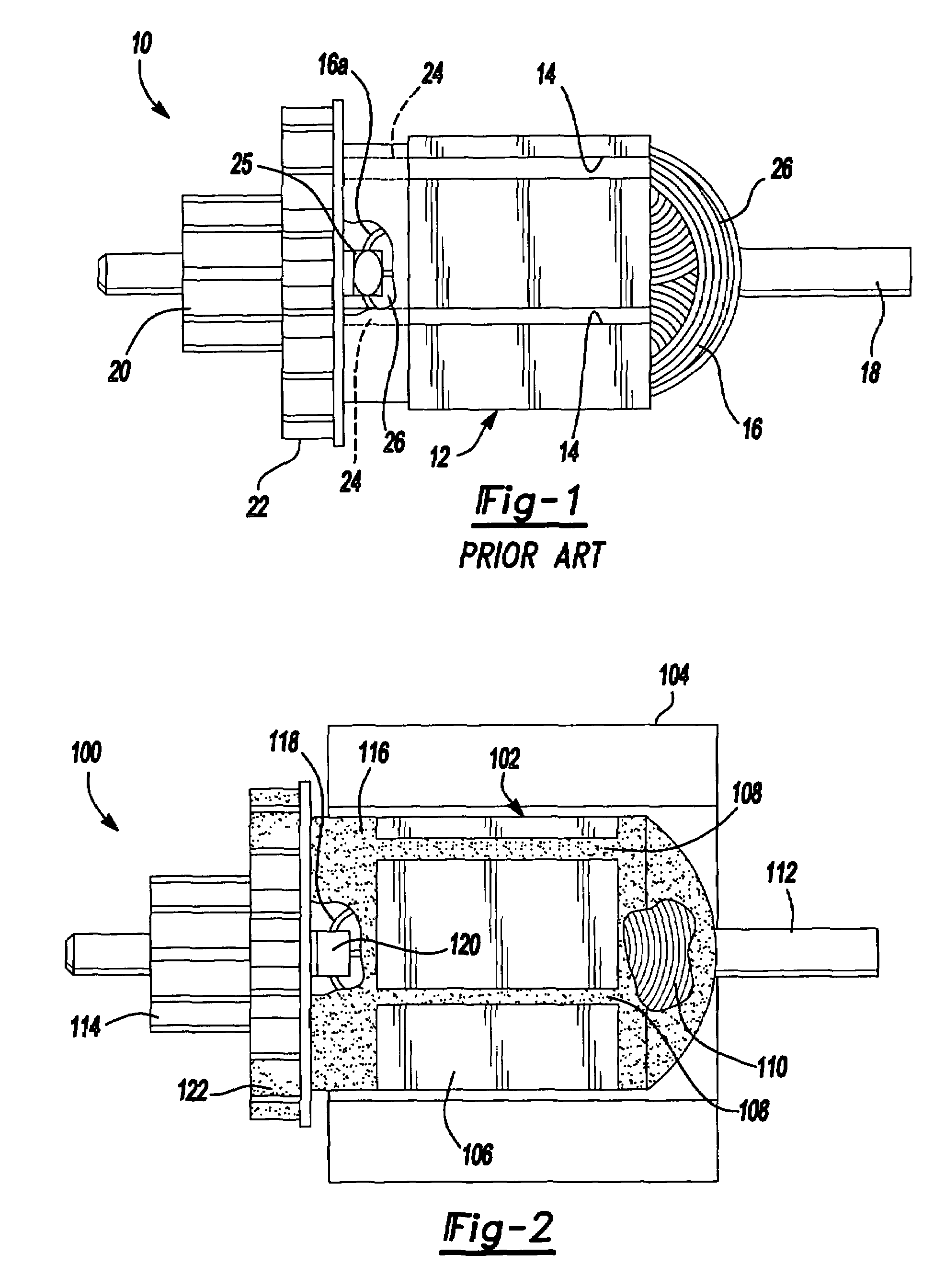
[0018]Referring to FIG. 1, there is illustrated a prior art armature 10 made in accordance with a conventional manufacturing process incorporating the trickle resin application steps described hereinbefore. The armature 10 incorporates a lamination stack 12 having a plurality of longitudinal slots 14 disposed circumferentially therearound. Wound within the slots 14 is a large plurality of magnet wires 16 forming coils. An armature shaft 18 extends coaxially through the lamination stack 12 and includes a commutator 20. An independently formed plastic fan 22 is secured, typically by adhesives, to the lamination stack 14. The fan 22 typically includes a plurality of legs 24 which project into the slots 14, thus taking up space which would more preferably be occupied by the magnet wires 16. Trickle resin 26 is applied over the magnet wires 16, in the slots 14, and also at the tangs 25 where the ends of the magnet wires 16a attach to the commutator 20.

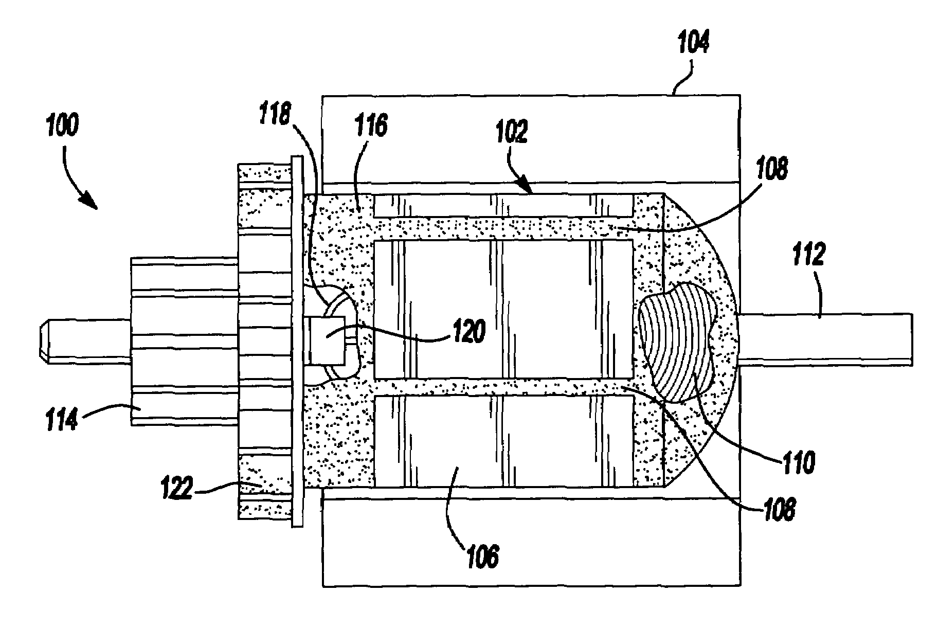
[0019]Referring now to FIG. 2, a mot...


PUM

PropertyMeasurementUnit
Densityaaaaaaaaaa
Moldableaaaaaaaaaa
Electrical conductoraaaaaaaaaa

Abstract

An electric motor having an armature which includes a coating of thermally conductive plastic applied in a conventional injection molding process. The armature also includes a fan which is integrally formed from the thermally conductive plastic applied to the armature. This completely eliminates the need to apply one or more coatings of a trickle resin to the armature. It also eliminates the need to separately form and secure a fan by a suitable adhesive to the armature, which together significantly simplifies the manufacturing and cost of the armature. The plastic coating also better fills the spaces between the magnet wires, thus promoting even more efficient cooling and better holding of the magnet wires stationary relative to one another. The thermally conductive plastic coating may be mixed with other suitable materials to provide a density approximately equal to the magnet wires. This eliminates the need to balance the armature after the injection molding step.

Description

CROSS REFERENCE TO RELATED APPLICATIONS[0001]This application is a divisional of U.S. application Ser. No. 09 / 836,517 filed Apr. 17, 2001 (abandoned), which is a continuation-in-part of U.S. application Ser. No. 09 / 756,959 filed Jan. 9, 2001 (abandoned).TECHNICAL FIELD[0002]This invention relates to electric motors, and more particularly to an electric motor having an armature which is at least structurally encased within a thermally conductive plastic, and wherein a fan is integrally formed from a portion of the thermally conductive plastic at one end of the armature.BACKGROUND OF THE INVENTION[0003]Electric motors are used in a wide variety of applications involving power tools such as drills, saws, sanding and grinding devices, yard tools such as edgers and trimmers, just to name a few such tools. These devices all make use of electric motors having an armature and a stator. The armature is typically formed from a lamination stack around which a plurality of windings of magnet wi...

Claims


Application Information

Patent Timeline
IPC IPC(8): H02K15/00H02K1/04H02K3/44H02K3/30H02K3/487H02K3/50H02K3/51H02K7/04H02K9/06H02K9/22H02K13/00H02K13/04H02K15/12H02K15/16
CPCH02K9/06H02K13/006H02K13/04Y10T29/49012Y10T29/49009
Inventor DU, HUNG T.
Owner BLACK & DECKER INC
Why Eureka
Try Eureka