
Fuel vapor separator

a technology of vapor separator and fuel, which is applied in the direction of liquid fuel feeder, combustion air/fuel air treatment, machines/engines, etc., can solve the problems of heavy metal bodies, clogging of water or coolant passages in metal bodies, and high manufacturing costs, so as to reduce or eliminate, improve water passage and coolant flow arrangement, and reduce the effect of clogging

Inactive Publication Date: 2006-03-21
WALBRO ENGINE MANAGEMENT
View PDF76 Cites 45 Cited by
  • Summary
  • Abstract
  • Description
  • Claims
  • Application Information

AI Technical Summary

Benefits of technology

[0006]Objects, features and advantages of the presently preferred embodiments of the fuel vapor separator include providing a polymeric body for a fuel vapor separator that reduces or eliminates the need to machine, plate, coat or otherwise treat the body, provides reliable venting and internal pressure control in the fuel vapor separator, provides an improved water passage and coolant flow arrangement, resists plugging of the coolant flow passage, provides improved hot fuel handling and vapor handling, significantly reduces or eliminates fuel foaming, is of relatively compact design, can be mounted in different locations relative to an engine, is light weight, corrosion proof and of relatively simple design and economical manufacture and assembly.

Problems solved by technology

The metal bodies tend to be heavy and expensive to manufacture.
Also, water or coolant passages machined in the metal bodies can become plugged with debris in or carried by the coolant and debris resulting from corrosion of the water passage itself.

Method used


Image

  • Fuel vapor separator
  • Fuel vapor separator
  • Fuel vapor separator

Examples


Embodiment Construction

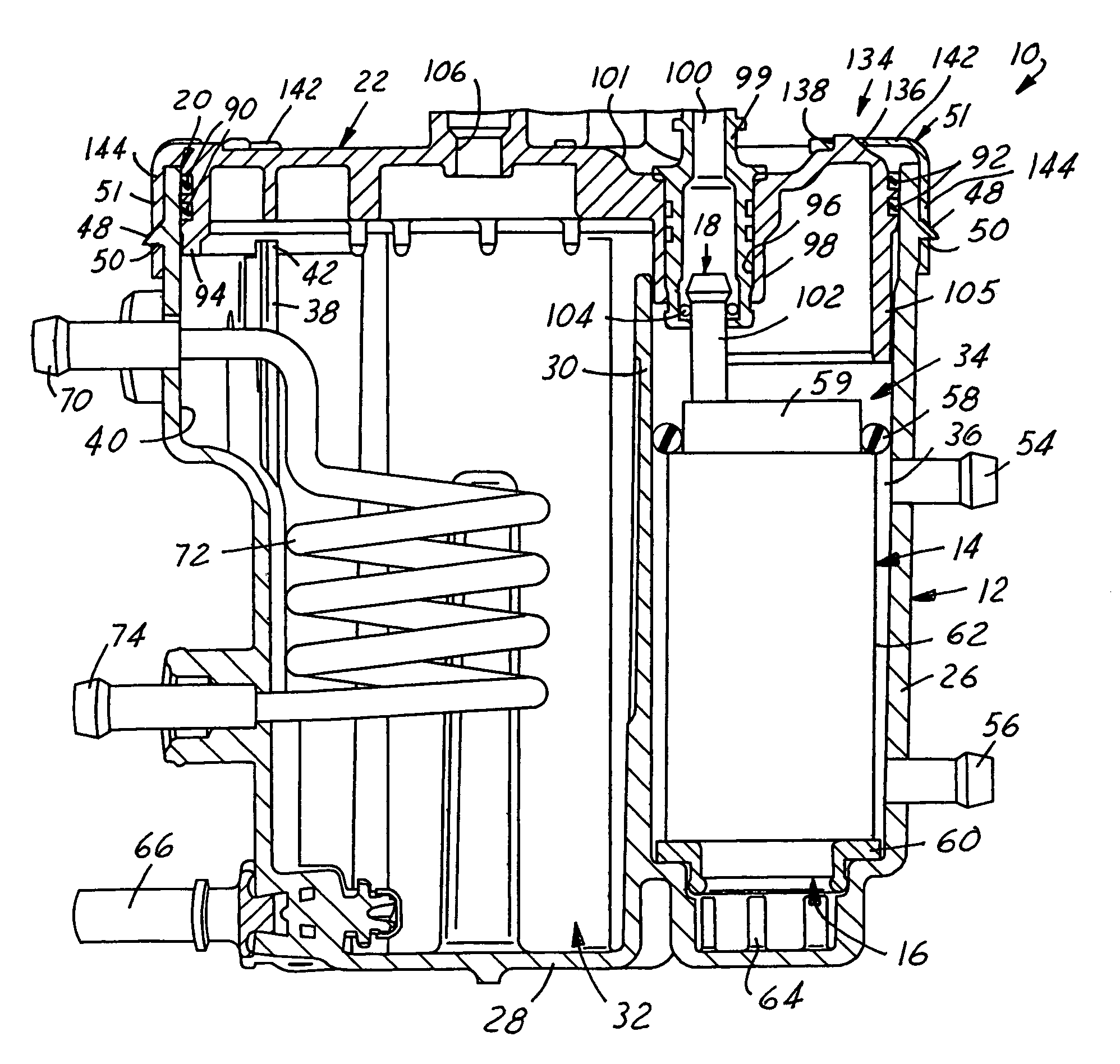
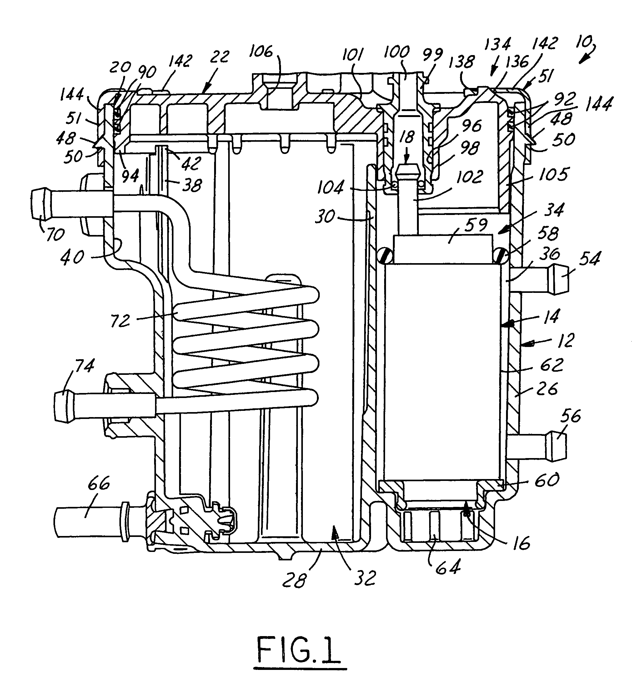
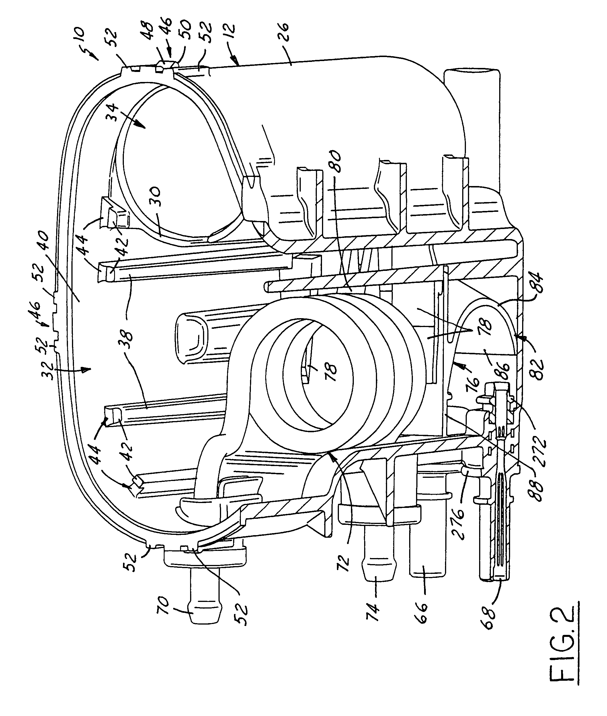
[0037]Referring in more detail to the drawings, FIG. 1 illustrates a fuel vapor separator 10 having a main body 12 formed of a polymeric material that is adapted to receive a supply of liquid fuel and provide a substantially vapor free supply of liquid fuel to the inlet of a fuel pump 14. The fuel pump 14 is preferably carried by the fuel vapor separator 10 and may be an electric motor driven fuel pump having an inlet 16 in communication with the supply of liquid fuel in the main body 12 and an outlet 18 through which pressurized fuel is discharged for delivery to an engine. Desirably, the main body 12 is generally bowl shaped and has an open upper end 20 that may be closed by a suitable lid 22 that is preferably also formed of a polymeric material. The lid 22 preferably carries a vapor vent valve 24 (FIG. 9) to facilitate venting fuel vapors from the fuel vapor separator 10 and to control the internal pressure of the fuel vapor separator 10.

[0038]In more detail, the main body 12 of...


PUM


Abstract

A fuel vapor separator includes a polymeric body that preferably has a polymeric canister and a polymeric lid secured to the canister to define a liquid tight enclosure. The enclosure is preferably divided into at least two chambers. One chamber preferably receives liquid fuel and communicates with a heat exchanger to cool the supply of liquid fuel therein. Vapor is trapped in a vapor dome area above the liquid fuel and is vented through a vent valve carried by the fuel vapor separator. The other chamber of the enclosure preferably receives a high pressure fuel pump adapted to receive liquid fuel from the first chamber, and to deliver liquid fuel under pressure to the engine. Preferably, the chamber in which the fuel pump is received is communicated with a coolant to facilitate cooling the fuel pump in use.

Description

FIELD OF THE INVENTION[0001]The present invention relates generally to fuel systems for internal combustion engines, and more particularly to a fuel vapor separator in such a fuel system.BACKGROUND OF THE INVENTION[0002]Some combustion engines include a fuel pump assembly having a high pressure fuel pump that delivers fuel under pressure to the engine, and a fuel vapor separator that acts as a fuel reservoir for supplying fuel to the high pressure fuel pump. The fuel pump delivers fuel to a fuel rail and associated fuel injectors. A fuel pressure regulator controls the fuel pressure within the rail and may be mounted on the return or downstream end of the rail with an exhaust or outlet of the fuel pressure regulator communicating with the fuel vapor separator through a fuel return line.[0003]The interior volume of the fuel vapor separator is generally held at a substantially lower pressure than the fuel rail. In addition, the fuel returned to the fuel vapor separator is often heated...

Claims


Application Information

Patent Timeline
IPC IPC(8): F02M33/02
CPCF02M37/20
Inventor COTTON, KENNETH J.KING, ERIC L.SMITH, ROGER N.
Owner WALBRO ENGINE MANAGEMENT
Learn More