Fastening element

a technology of fastening elements and fixing screws, applied in the direction of nails, screws, bolts, etc., can solve the problems of tip bending up and kinking

Active Publication Date: 2006-03-21
HILTI AG
View PDF22 Cites 18 Cited by
  • Summary
  • Abstract
  • Description
  • Claims
  • Application Information

AI Technical Summary

Benefits of technology

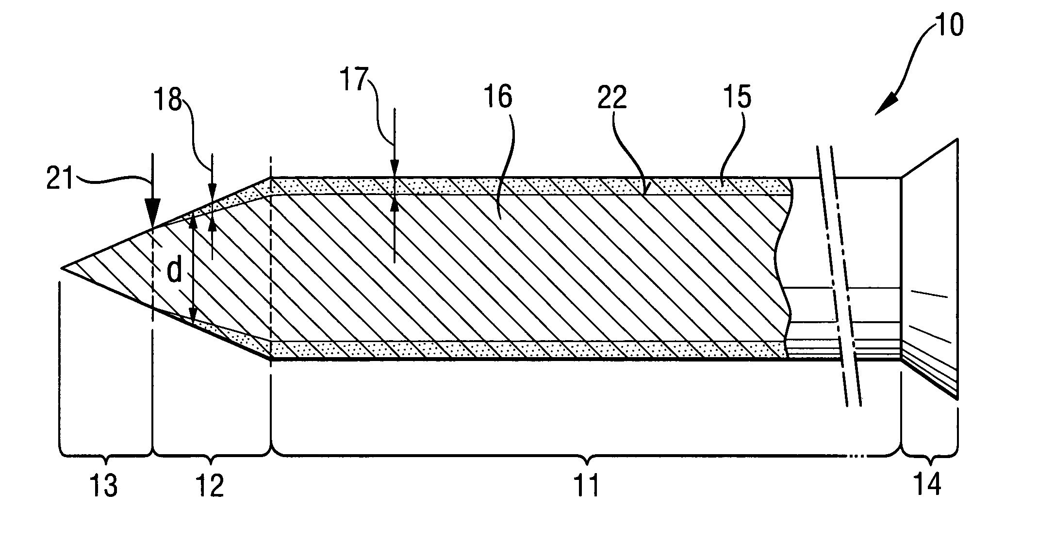
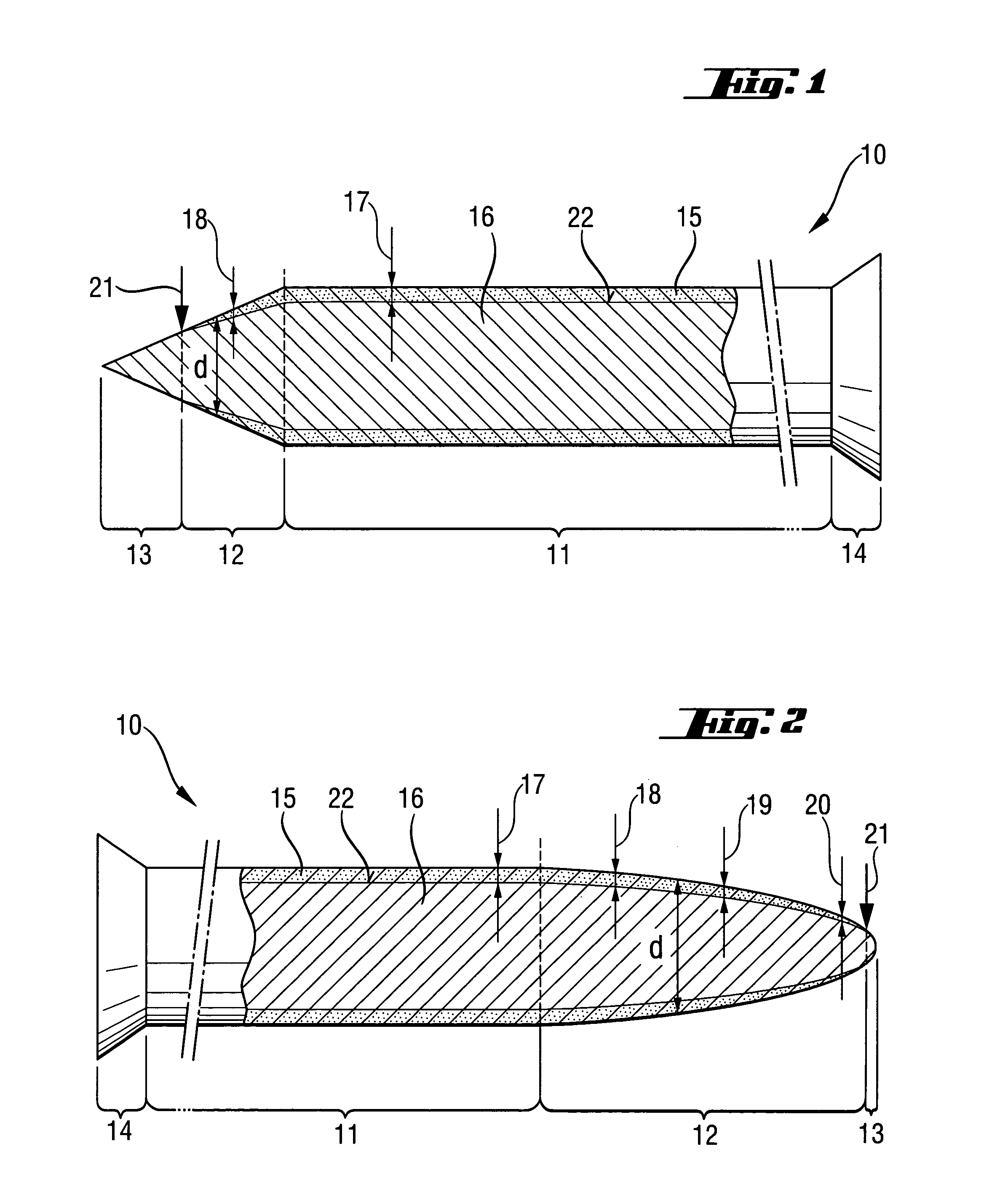
[0012]Advantageously, the diameter of the transition region gradually tapers toward the tip, so that the transition region becomes, from a manufacturing point of view, a part of the tip. Thereby, the transition region is formed simultaneously with the tip, which reduces manufacturing costs.
[0013]Advantageously, the rim zone has, in the region of the stem, a thickness of from 20 to 200 μm, preferably, from 40 to 100 μm. This permits to optimally reduce the brittleness of the fastening element in its stem region. As a result of reduced brittleness, no fissures are formed in the region of the stem. Advantageously, the rim zone has a hardness from 150 to 500 HV, preferably from 200 to 300 HV, which further reduces the danger of formation of fissure.
[0014]Preferably, the core has a hardness from 550 to 700 HV. This insures that the fastening element according to the invention has good drive-in characteristic and a dimensional stability, in particular, when being driven in a hard material, such as steel and concrete.

Problems solved by technology

A drawback of fastening elements of the types described above and which have a relatively soft ferritic outer zone consists in a possibility that the tip would bend-up, become kinked upon striking an added material (e.g., pebbles) in concrete.

Method used


Image

  • Fastening element
  • Fastening element
  • Fastening element

Examples


Embodiment Construction

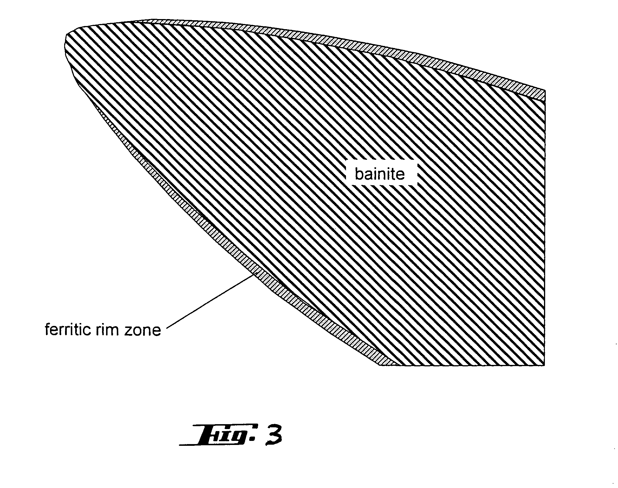
[0021]A fastening element 10 according to the present invention, which is shown in FIG. 1, is formed as a nail. The fastening element 10 has a head 14 and a stem 11 that adjoins the head 14. At its end remote from the head 14, the stem 11 has a tip 13. The fastening element 10 has a rim zone 15 extending over the stem 11 and a transition region 12 from the stem 11 to the tip 13. The rim zone 15 consists of ferritic decarburized steel having a Vickers hardness from 200 to 300 HV. However, the steel in the rim zone 15 can also have a hardness from 150 to 500 HV. The rim zone 15 is located outside of a core 16 that consists of bainitic or martensitic steel having a hardness of about from 550 to 700 HV. The thickness of the rim zone 15 in the region of the stem 11 amounts to about from 40 to 100 μm. However, this thickness can lie in a range from 20 to 200 rim. In the transition region 12, the thickness of the rim zone 15 is continuously reduced from a thickness 17 in the region of the ...


PUM


Abstract

A fastening element which has a core (16) of a relatively hard, carburized steel and a ferritic rim zone (15) of a less hard, low-carbon steel, includes a stem (11), a head (14) provided at one end of the stem (11), a tip (13) provided at an opposite end of the stem (11), and a transition region (12) extending between the stem (11) and the tip (13) and in which a thickness (18, 19, 20) of the ferritic rim zone (15) gradually diminishes from the stem (11) in a direction toward the tip (13) to a nill value (21), so that the tip (13) is free from the ferritic rim zone (15).

Description

BACKGROUND OF THE INVENTION[0001]1. Field of the Invention[0002]The present invention relates to a fastening element having a core of a relatively hard carburized steel and a ferritic rim zone of a less hard, low-carbon steel and including a stem, a head provided at one end of the stem, and a tip provided at an opposite end of the stem.[0003]2. Description of the Prior Art[0004]Fastening elements of the type described above, such as nails, bolts and the like and which are made of steel, are used for attaching or fastening objects to hard materials such as concrete, metal, stone and the like. The fastening elements have a stem provided at its end, which faces in the setting direction, with a tip, and at its opposite end with a head having a diameter greater than that of the stem. The driving-in process is effected by applying blows to the head or by driving the fastening element in with a combustion energy-actuated setting tool.[0005]German Publication DE 4139 653A1 discloses a faste...

Claims


Application Information

Patent Timeline
Patent Type & Authority Patents(United States)
IPC IPC(8): F16B15/00F16B19/14
CPCF16B15/0092F16B19/14Y10S411/902Y10S411/901Y10S411/914
Inventor ALLAART, JANDIETZE, SVENEBERT, THORSTEN
Owner HILTI AG
Why Eureka
Try Eureka