Apparatus for aesthetic skin treatments

a technology for skin treatment and skin, applied in the field of skin aesthetics, can solve the problems of reducing the effect of light intensity, and maintaining other characteristics of light emitted by leds unchanged

Inactive Publication Date: 2006-03-21
WALNECK CHARLES T
View PDF25 Cites 44 Cited by
  • Summary
  • Abstract
  • Description
  • Claims
  • Application Information

AI Technical Summary

Benefits of technology

[0014]A primary object of the claimed invention is to provide a new apparatus for aesthetic skin treatments that provides improved results over previous devices.
[0019]The control console generally comprises a session timer display with controls, a massage control, a small pulsator control, a pause control, a large pulsator control, a Phase I control, a Phase II control and a Phase III control. The session timer has a two digit LED timer display controlled by two timer select controls that are provided for an operator to set the number of minutes that a particular session will last. The massage control 70 allows an operator to activate a vibration means within the large pulsator to provide a massaging action to the subject's skin when the large pulsator is being used.
[0022]The circuitry within the control console provides a frequency modulating means and a power output modulating means that control the emitting frequency and power output of the LEDs within the large pulsator and small pulsator. An operator of the apparatus can choose among three phases where the emitting frequency and power output of the LEDs are varied for different periods of time to achieve certain desired results. The modulation of the emitting frequency and power output of the LEDs provide a pulsating effect that manipulates the skin of a subject being treated.

Problems solved by technology

However, varying the wavelength of the light alone and maintaining other characteristics of the light emitted by the LEDs unchanged produces minimal results.

Method used


Image

  • Apparatus for aesthetic skin treatments
  • Apparatus for aesthetic skin treatments
  • Apparatus for aesthetic skin treatments

Examples


Embodiment Construction

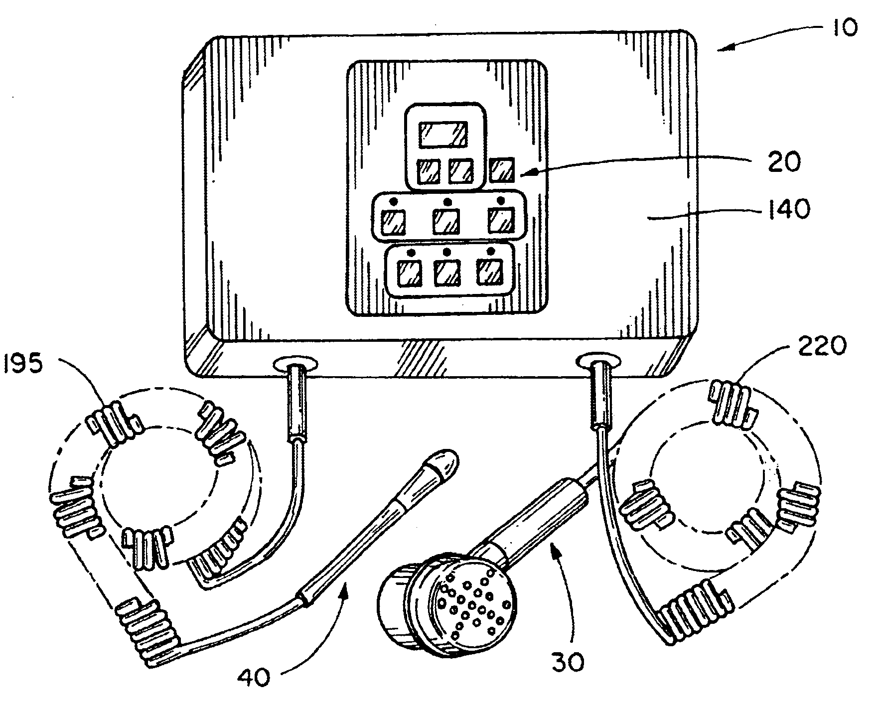
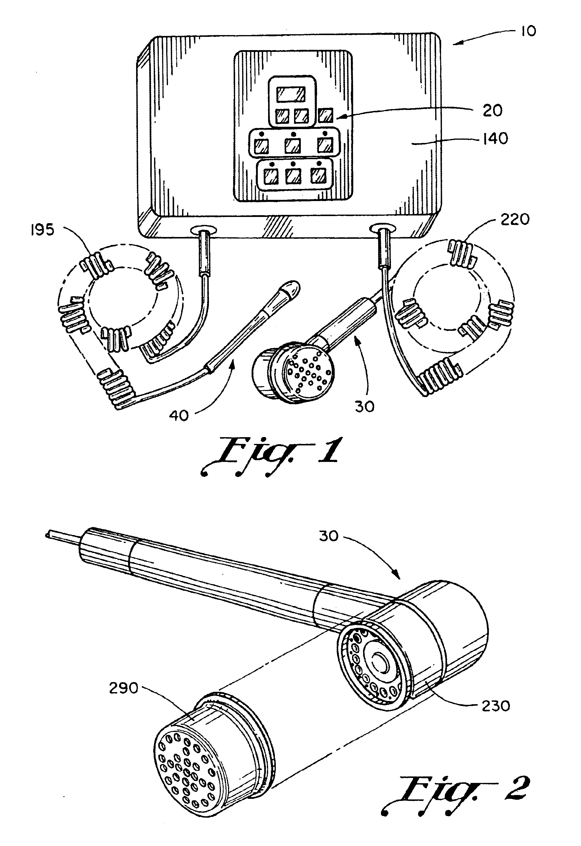
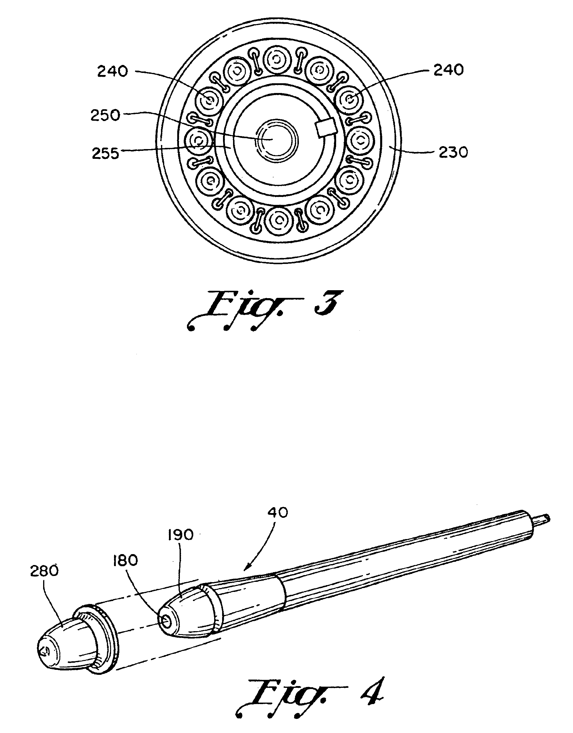
[0031]Turning now to the drawings, FIG. 1 shows the preferred embodiment of the apparatus 10 for aesthetic skin treatments. The preferred embodiment of the apparatus 10 generally comprises a control console 20, a large pulsator 30 having a plurality of light emitting diodes (LEDs) and a small pulsator 40 having a single LED.

[0032]FIG. 5 shows that the control console 20 generally comprises a session timer display 50 with controls 60, a massage control 70, a small pulsator control 80, a pause control 90, a large pulsator control 100, a Phase I control 110, a Phase II control 120, a Phase III control 130 and a power switch control (not shown). Each control has an LED adjacent the control that provides a visual indication as to the status of the particular control. The control console 20 may optionally have a unit lock key switch (not shown) to prevent unauthorized use of the apparatus 10. FIG. 8 shows a block diagram of the circuitry 135 that is contained within the control console ho...


PUM


Abstract

An apparatus for aesthetic manipulation of the skin having a large pulsator with plurality of light emitting diodes of at least two different wavelengths and a small pulsator with one light emitting diode is disclosed. A frequency modulator automatically modulates the emitting frequency of the tight emitting diodes to a plurality of different frequencies. A power output modulator is provided to modulate the power output of the light emitting diodes. A phase switching subsystem allows selection between a plurality of operating phases, each operating phase operating the frequency modulator and power output modulator in a different predetermined manner. Calibration subsystem connected in circuit with the light emitting diodes calibrates the power output of the light emitting diodes. A vibrator is provided to vibrate the large pulsator. A vibration switching subsystem selectively activates the vibrator.

Description

BACKGROUND OF THE INVENTION[0001]1. Field of the Invention[0002]The claimed invention generally relates to devices for aesthetic manipulation of the skin. More specifically, the claimed invention relates to a method and apparatus for aesthetic manipulation of the skin accomplished by modulation of the frequency, wavelength and output of light emitting diodes.[0003]2. Description of the Prior Art[0004]As segments of the population, such as the “baby boomer” generation, get older, the market for products that help reduce the signs of aging has drastically increased. One of the major areas of concern for many people is the reduction of wrinkles in facial skin. Many different types of facial creams have been developed over the years that claim to reduce wrinkling of the skin, but people have still sought better ways of addressing the problem. One of the newer approaches even includes injecting a form of botulism under the skin to smooth out wrinkles. However, people still seek new produ...

Claims


Application Information

Patent Timeline
Patent Type & Authority Patents(United States)
IPC IPC(8): A61B18/18A61B18/20A61H23/02A61N5/06
CPCA61N5/0616A61H23/02A61B18/203A61B2018/00452A61B2018/0047A61N2005/0659A61N2005/0644A61N2005/0652
Inventor WALNECK, CHARLES T.BRENNAN-MCCLURE, TAMI L.SANTEE, JAMES H.
Owner WALNECK CHARLES T
Why Eureka
Try Eureka