Composite reinforced electrical transmission conductor

a technology of electrical transmission and conductor, which is applied in the direction of insulated conductors, power cables, cables, etc., can solve the problems of success of current carrying conductors, and achieve the effects of less labor intensity, easy reheating, and the same strength

Inactive Publication Date: 2006-03-21
GIFT TECH LP
View PDF12 Cites 96 Cited by
  • Summary
  • Abstract
  • Description
  • Claims
  • Application Information

AI Technical Summary

Benefits of technology

[0025]It is also an object of the present invention to provide an electrical transmission cable of the type stated in which the ends of the cable can easily be spliced together at an on-site location and with much less labor intensity than the splicing of a steel core cable and at significantly less cost.
[0037]The actual splicing operation can be conducted more quickly and with less labor intensity then when attempting to splice steel core conductors together. In addition, and since the inner core is formed of a reinforced composite material, the spliced section has essentially the same strength as any other portion of the entire conductor.

Problems solved by technology

Heretofore, there have been numerous problems arising out of the use of the steel core, as identified above, although there has been no successful current carrying conductor which utilizes a reinforced plastic composite inner core.

Method used


Image

  • Composite reinforced electrical transmission conductor
  • Composite reinforced electrical transmission conductor
  • Composite reinforced electrical transmission conductor

Examples


Embodiment Construction

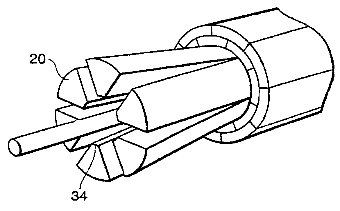
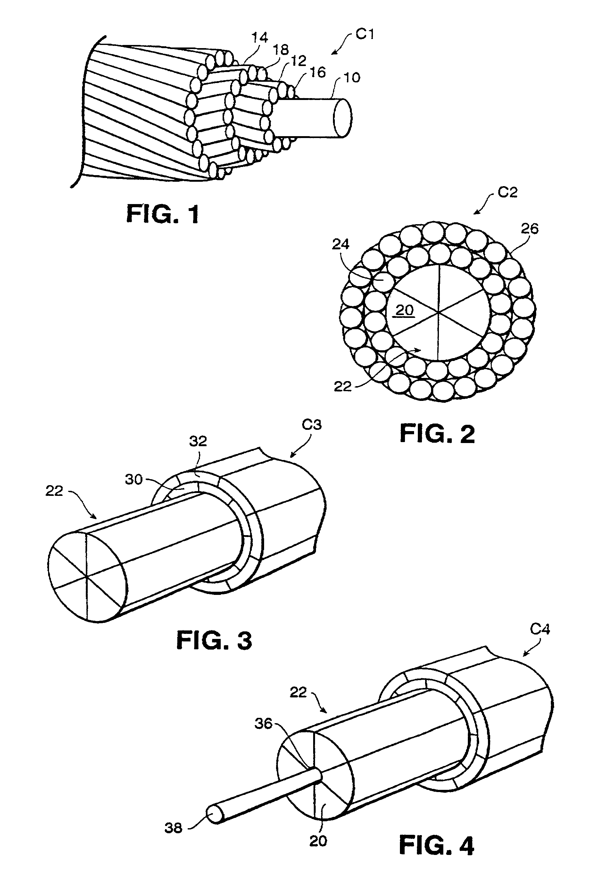
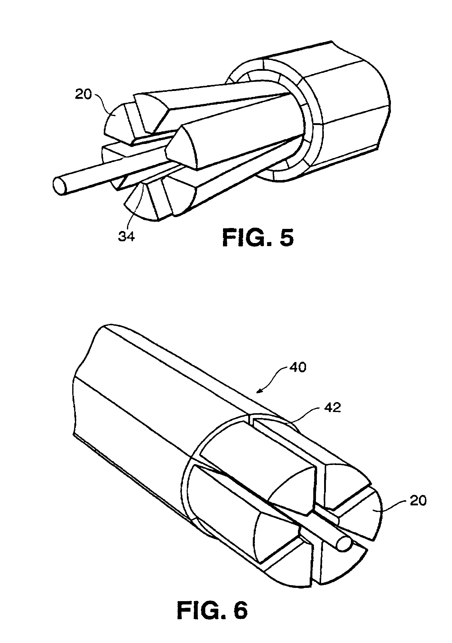
[0049]Referring now in more detail and by reference characters to the drawings, which illustrate preferred embodiments of the present invention, C1 illustrates an electrical transmission cable having a reinforced plastic composite load bearing core 10 and a plurality of outer layers of aluminum wire 12 and 14 extending thereabout.

[0050]By further reference to FIG. 1, it can be seen that the load bearing core 10 included a solid reinforced plastic composite member. Also, in the embodiment as illustrated in FIG. 1 and the subsequently illustrated and described embodiments, there are three outer aluminum layers 12, 18 and 14 (see FIG. 1), although it should be understood that any number of outer layers could be employed depending upon the desired thickness of the outer current conducting sheath to be formed over the core. It can be observed that in this construction, the cable C1 is similar in appearance to a conventional steel core cable. Consequently, it can be laid in the same fashi...


PUM

PropertyMeasurementUnit
breaking strengthaaaaaaaaaa
shallow angleaaaaaaaaaa
distanceaaaaaaaaaa

Abstract

A composite reinforced electrical transmission conductor primarily designed for transmission of electrical signals. The conductor is comprised of a reinforced plastic composite inner core along with an outer highly electrically conductive sheath therearound. In this way, the inner core provides the necessary strength and the outer sheath provides for transmission of the electrical signals. In a preferred embodiment, the reinforced composite core is comprised of individual sections which cooperate together to provide the necessary loading capabilities. Further, a fiber optic cable may also be carried by the composite reinforced core. A splicing arrangement for securing ends of the cable together is also provided.

Description

CROSS-REFERENCE TO RELATED APPLICATION[0001]This application is a continuation of U.S. application Ser. No. 09 / 500,285, filed on Feb. 8, 2000, now abandoned, the contents of which are fully incorporated herein by reference.BACKGROUND OF THE INVENTION[0002]1. Field of the Invention[0003]This invention relates in general to certain new and useful improvements in electrical transmission cables and, more particularly, to electrical transmission cables which have a composite reinforced component to provide loading capabilities.[0004]2. Brief Description of the Related Art[0005]In electrical conductors and, particularly, long distance electrical conductors, copper was frequently employed because of its superior conductive properties and was widely used until about the time of World War II, at which point its primary use was directed to war efforts. Prior to that time, and even thereafter, conductor technology and the selection and mixture of different wire materials has evolved gradually ...

Claims


Application Information

Patent Timeline
Patent Type & Authority Patents(United States)
IPC IPC(8): H01B7/18G02B6/44H01B5/10H01B11/22H01B13/00H02G1/02H02G1/14H02G7/02
CPCG02B6/255G02B6/4416G02B6/4467H01B5/105H01R4/62H02G1/02H02G15/18H02G7/04Y10T29/5187Y10T29/49174Y10T428/2933Y10T29/49117Y10T29/49194G02B6/564
Inventor GOLDSWORTHY, WILLIAM BRANDTKORZENIOWSKI, GEORGE
Owner GIFT TECH LP
Why Eureka
Try Eureka