Accuracy automated optical time domain reflectometry optical return loss measurements using a "Smart" Test Fiber Module

a technology of optical return loss and test fiber, applied in the direction of optical apparatus testing, instruments, structural/machine measurement, etc., can solve the problems of optical return loss, inability to accurately measure the properties of optical fibers, etc., to achieve suitable signal-to-noise ratio and eliminate saturation condition of detector modules

Inactive Publication Date: 2006-03-21
NETTEST NEW YORK
View PDF2 Cites 46 Cited by
  • Summary
  • Abstract
  • Description
  • Claims
  • Application Information

AI Technical Summary

Benefits of technology

[0012]In another aspect, the invention features a method of performing automated optical time domain reflectometry optical return loss measurements on an optical fiber under test. The method comprises the steps of providing a launch optical fiber module having at least one predefined characteristic and having a first end and a second end; connecting the second end of the launch optical fiber module to a first end of an optical fiber under test, the optical fiber under test having a second end disposed at a length from the first end; illuminating the first end of the launch optical fiber module with applied illumination controllable in intensity with respect to time; detecting return illumination with a detector module having adjustable gain, the return illumination reflected by at least one of the launch optical fiber module and the optical fiber under test; as necessary to eliminate a saturation condition of the detector module, controlling at least one of the applied illumination and the gain of the detector module; as necessary to attain a suitable signal-to-noise ratio from the return illumination from the launch optical fiber module and the optical fiber under test, repeating the above steps of illuminating and detecting; and determining automatically from the return illumination and from the at least one of the predefined characteristic an optical return loss characteristic of the optical fiber under test.

Problems solved by technology

While OTDR instruments and the OTDR method have been used for some years, there are often issues relating to the accuracy of measurements made by inexperienced users.
As is clear from reviewing this document, the process of measuring the properties of an optical fiber is demanding and requires care and precision for a successful outcome.
Optical return loss (ORL) can cause problems in Dense Wave Division Multiplex (DWDM) and other high-speed optical transmission systems used in communication networks.
ORL can affect system performance by causing higher Bit Error Rates (BER) at a receiver and by causing transmitter damage if the output power requirements are unstable.

Method used


Image

  • Accuracy automated optical time domain reflectometry optical return loss measurements using a "Smart" Test Fiber Module
  • Accuracy automated optical time domain reflectometry optical return loss measurements using a "Smart" Test Fiber Module
  • Accuracy automated optical time domain reflectometry optical return loss measurements using a "Smart" Test Fiber Module

Examples


Embodiment Construction

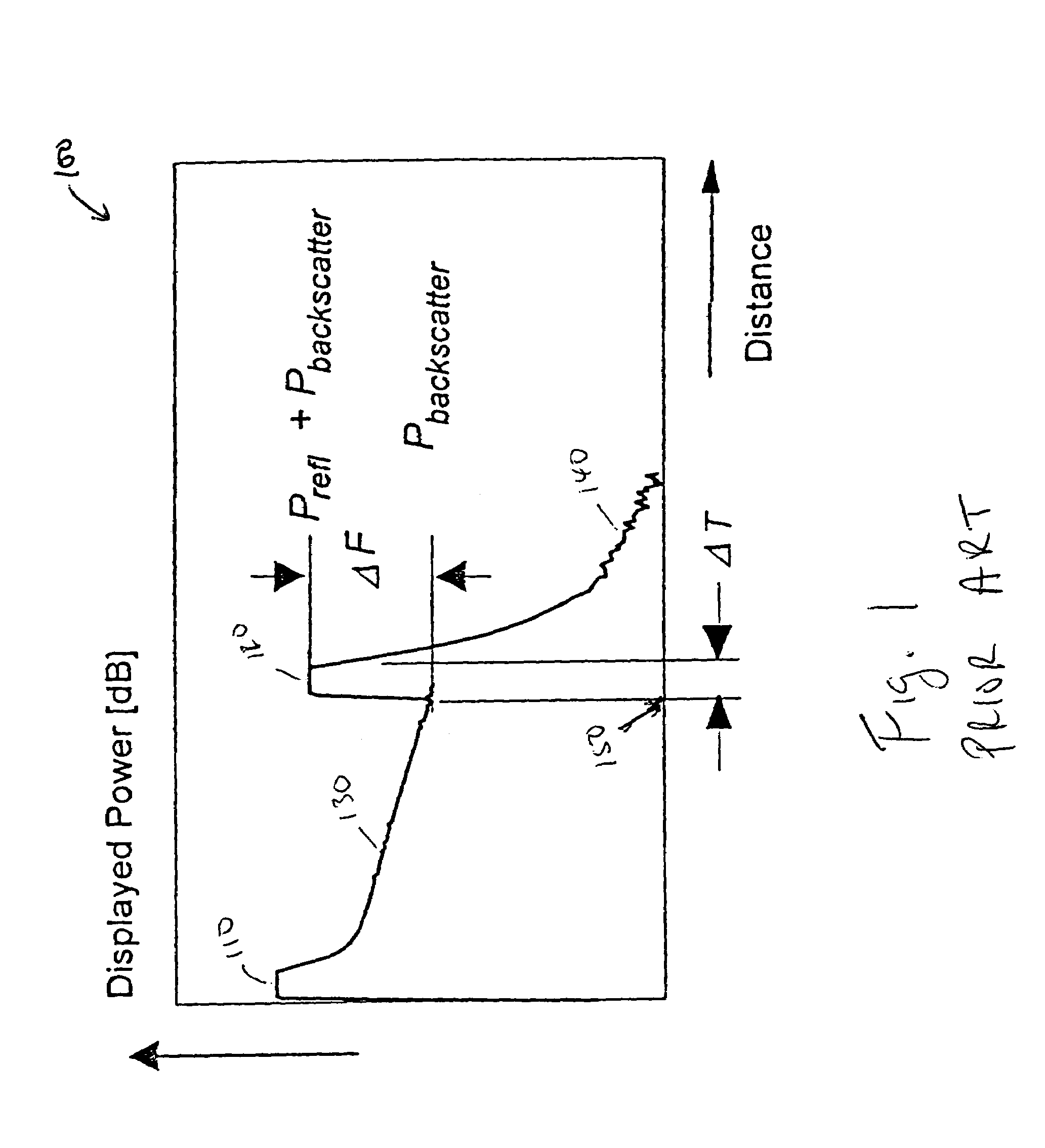
[0026]Light traveling along an optical fiber becomes attenuated as it travels along the fiber. Light is attenuated by a variety of different mechanisms, including absorption by the fiber, escaping from the fiber (due to imperfections or due to excessive bending of the fiber), Rayleigh scattering, and by Fresnel reflection (which occurs when there is a sudden change in the optical index (or index of refraction) of the material through which the light is traveling. Reflectance (or Fresnel Reflection) is the term used to refer to an optical loss mechanism involving reflection that takes place at a single component, such as the end connectors on the fiber under test (hereinafter “FUT”), or any mechanical connection within the FUT. The amount of reflection at a connector, break or mechanical splice depends on a number of factors, including how clean the break is; how much the index of refraction (hereinafter “IOR”) changes when the light leaves the fiber; and the connector polish. In fib...


PUM

PropertyMeasurementUnit
wavelengthsaaaaaaaaaa

Abstract

The invention provides automated systems and methods for measuring ORL of fibers under test. A computer-based test instrument using OTDR tests fibers with the help of a STFM having predefined characteristics that are recorded in a machine-readable memory. The information recorded in the memory is accessible to the computer-based instrument and is used to calibrate a power level of an illumination source in real time using the reflectance response of the STFM. The calibrated illumination power allows the instrument to automatically determine the ORL of the fiber being tested with precision, and without requiring the intervention of an operator. The instrument also has the capability to automatically sense the presence of a test fiber, and to automatically attenuate the reflectance signal to remove a saturation condition by controlling at least one of the illumination, the detector gain, an amplifier gain, and an optional in-line optical attenuator.

Description

FIELD OF THE INVENTION[0001]The invention relates to systems and methods for determining losses in optical fiber segments in general and particularly to systems and methods for measuring such losses using a calibrated fiber segment and automated systems and methods for determining such losses.BACKGROUND OF THE INVENTION[0002]A widely used method of determining light attenuation in a fiber, which attenuation is observed as an Optical Return Loss (hereinafter “ORL”), utilizes an optical time domain reflectometer instrument (hereinafter “OTDR”), and the measurement process is referred to as optical time domain reflectometry (also referred to hereinafter as “OTDR”). While OTDR instruments and the OTDR method have been used for some years, there are often issues relating to the accuracy of measurements made by inexperienced users. The calibration of OTDR instruments is known, as described for example in the 23 page document entitled “Calibration of Optical Time-Domain Reflectometers,” pu...

Claims


Application Information

Patent Timeline
Patent Type & Authority Patents(United States)
IPC IPC(8): G01N21/00G01M11/00
CPCG01M11/3109
Inventor BRIDGE, GARY D.SOULE, GREGORY
Owner NETTEST NEW YORK
Why Eureka
Try Eureka