Using an external spiral servo writer to write spiral tracks to a disk to facilitate writing product servo sectors to the disk

a technology of spiral tracks and spiral servos, which is applied in the direction of maintaining head carrier alignment, digital recording, instruments, etc., can solve the problems of external servo writers being expensive and requiring a clean room environment, external servo writers being an expensive bottleneck in the disk drive manufacturing process, and the calibration process inevitably showing some degree of error

Inactive Publication Date: 2006-03-21
WESTERN DIGITAL TECH INC
View PDF9 Cites 128 Cited by
  • Summary
  • Abstract
  • Description
  • Claims
  • Application Information

AI Technical Summary

Problems solved by technology

However, external servo writers are expensive and require a clean room environment so that a head positioning pin can be inserted into the head disk assembly (HDA) without contaminating the disk.
Thus, external servo writers have become an expensive bottleneck in the disk drive manufacturing process.
However, the calibration process will inevitably exhibit some degree of error and the dynamics of the disk drive will change between seeks inducing errors in the radial position of the spiral tracks.
Dynamic errors which degrade the spiral tracks written during an open loop seek include vibration of the HDA, flutter and non-repeatable run-out of the disk and spindle bearings, stiction and non-repeatable run-out of the pivot bearings, windage on the head and arm, and flex circuit bias, windage and vibration.
Errors in writing the spiral tracks will propagate to the product servo sectors, thereby degrading the operating performance of the disk drive and reducing the manufacturing yield.
In order to initially synchronize the PLL to the missing bits the head must servo accurately in a circular path since PLL phase error can occur due to actual timing errors or radial tracking errors.
Conversely, PLL phase errors cause radial tracking errors making it difficult to simultaneously maintain the head in a circular path by servoing on the spiral tracks while attempting to synchronize the PLL to the missing bits.

Method used


Image

  • Using an external spiral servo writer to write spiral tracks to a disk to facilitate writing product servo sectors to the disk
  • Using an external spiral servo writer to write spiral tracks to a disk to facilitate writing product servo sectors to the disk
  • Using an external spiral servo writer to write spiral tracks to a disk to facilitate writing product servo sectors to the disk

Examples


Embodiment Construction

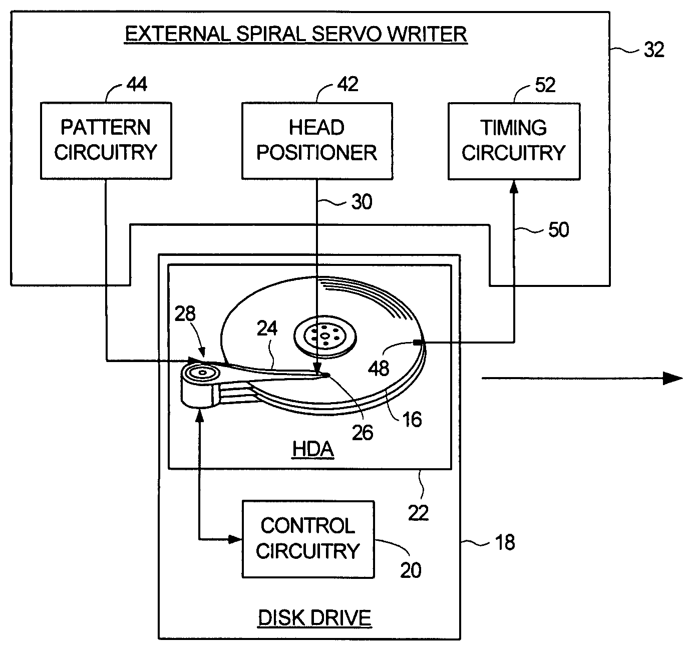
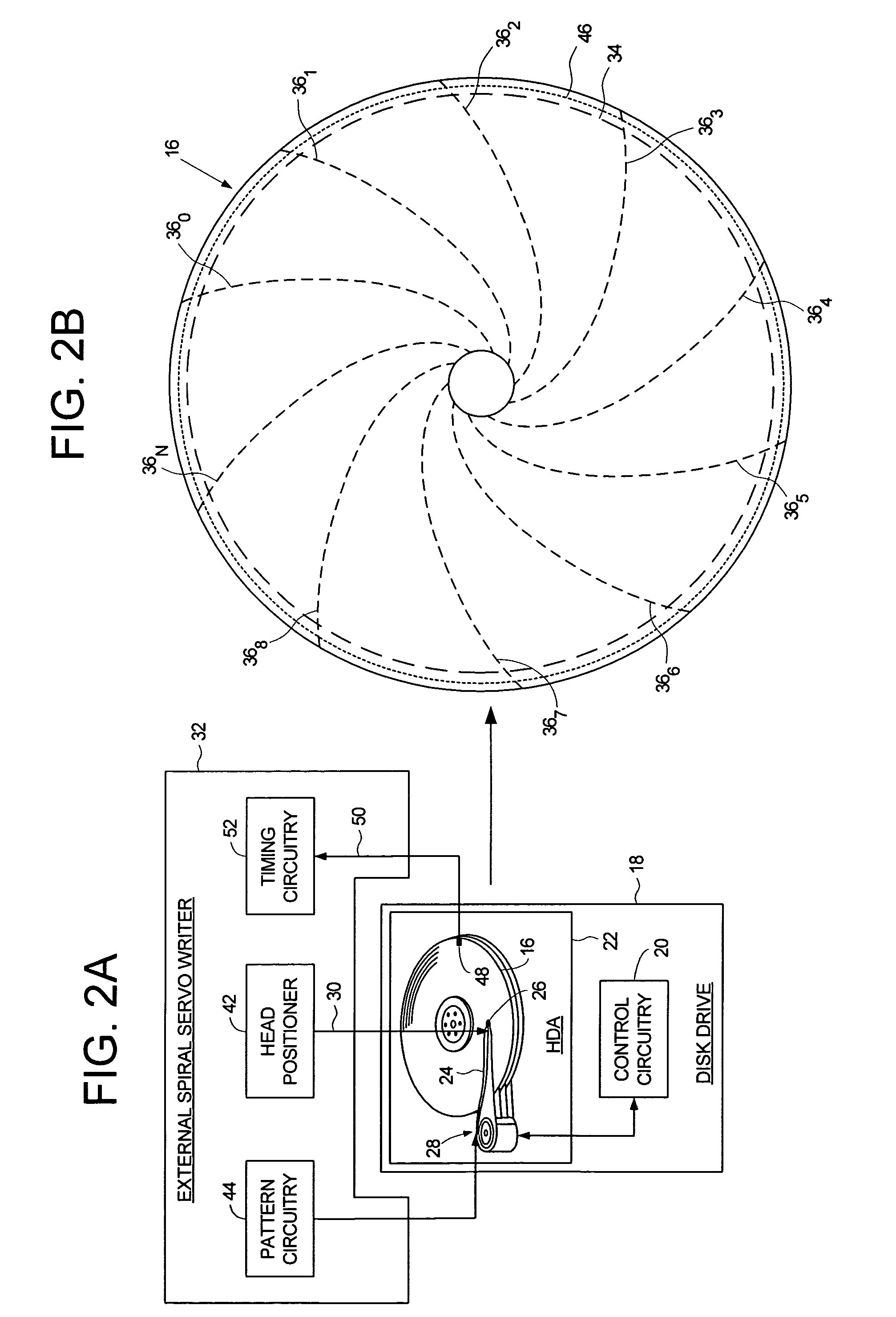
[0021]FIGS. 2A and 2B illustrate an embodiment of the present invention for writing product servo sectors to a disk 16 of a disk drive 18. The disk drive 18 comprises control circuitry 20 and a head disk assembly (HDA) 22 comprising the disk 16, an actuator arm 24, a head 26 connected to a distal end of the actuator arm 24, and a voice coil motor 28 for rotating the actuator arm 24 about a pivot to position the head 26 radially over the disk 16. A head positioning pin 30 of an external spiral servo writer 32 is inserted into the HDA 22, wherein the head positioning pin 30 for engaging the actuator arm 24. The external spiral servo writer 32 derives a radial location of the head 26 and actuates the head positioning pin 30 in response to the radial location of the head 26 in a closed loop system to rotate the actuator arm about the pivot in order to position the head radially over the disk 16 while writing a plurality of spiral tracks 360–36N, wherein each spiral track comprises a hig...


PUM

PropertyMeasurementUnit
frequencyaaaaaaaaaa
outer diameteraaaaaaaaaa
inner diameteraaaaaaaaaa

Abstract

A method of writing product servo sectors to a disk of a disk drive is disclosed. An external spiral servo writer writes a plurality of spiral tracks to the disk by actuating in a closed loop system a head positioning pin inserted into the disk drive. Each spiral track comprises a high frequency signal interrupted at a predetermined interval by a sync mark. The high frequency signal and sync marks in the spiral tracks are demodulated to maintain synchronization of a servo write clock as well as maintain the head along a circular target path while writing product servo sectors to the disk.

Description

[0001]This application is a divisional of co-pending patent application Ser. No. 10 / 769,387 filed on Jan. 31, 2004.BACKGROUND OF THE INVENTION[0002]1. Field of the Invention[0003]The present invention relates to disk drives for computer systems. More particularly, the present invention relates to using an external spiral servo writer to write spiral tracks to a disk to facilitate writing product servo sectors to the disk.[0004]2. Description of the Prior Art[0005]When manufacturing a disk drive, product servo sectors 20–2N are written to a disk 4 which define a plurality of radially-spaced, concentric data tracks 6 as shown in the prior art disk format of FIG. 1. Each product servo sector (e.g., servo sector 24) comprises a preamble 8 for synchronizing gain control and timing recovery, a sync mark 10 for synchronizing to a data field 12 comprising coarse head positioning information such as a track number, and servo bursts 14 which provide fine head positioning information. During n...

Claims


Application Information

Patent Timeline
Patent Type & Authority Patents(United States)
IPC IPC(8): G11B5/09G11B5/596G11B21/02
CPCG11B5/59661G11B5/59633
Inventor AGARWAL, VINAY K.CHUE, JACK M.CLOKE, ROBERT L.
Owner WESTERN DIGITAL TECH INC
Why Eureka
Try Eureka