
Scaleable interconnect structure utilizing quality-of-service handling

Inactive Publication Date: 2006-03-21
INTERACTIC HLDG LLC
View PDF9 Cites 34 Cited by
  • Summary
  • Abstract
  • Description
  • Claims
  • Application Information

AI Technical Summary

Benefits of technology

[0011]Nodes of the structure have a plurality of input ports and output ports. Data entering one or more of the input ports moves down the structure thereby making progress to a target or goal specified in the data. Guidance of data through the structure is aided by control signals between nodes from nodes on a given level to nodes on a more uppermost level. A routing node on a given level can route a packet to a receiving node on a lower level provided that: (1) the node on the lower level is on a route leading to a target of the packet, and (2) the control signals to the routing node indicate that the receiving node is not blocked. In some embodiments, an additional condition is that the quality of service level of the packet is at least a predetermined level with respect to a minimum level of quality of service to descend to a lower level. The predetermined level depends upon the location of the routing node. The technique allows higher quality of service packets to outpace lower quality of service packets early in the progression through the interconnect structure. The technique is similar to seeding favorites in a race in the front row at the start.

Problems solved by technology

Heavy information or packet traffic in a network or interconnection system can cause congestion, creating problems that result in the delay or loss of information.
Heavy traffic can cause the system to store information and attempt to send the information multiple times, resulting in extended communication sessions and increased transmission costs.
Conventionally, a network or interconnection system may handle all data with the same priority so that all communications are similarly afflicted by poor service during periods of high congestion.

Method used


Image

  • Scaleable interconnect structure utilizing quality-of-service handling
  • Scaleable interconnect structure utilizing quality-of-service handling
  • Scaleable interconnect structure utilizing quality-of-service handling

Examples


Embodiment Construction

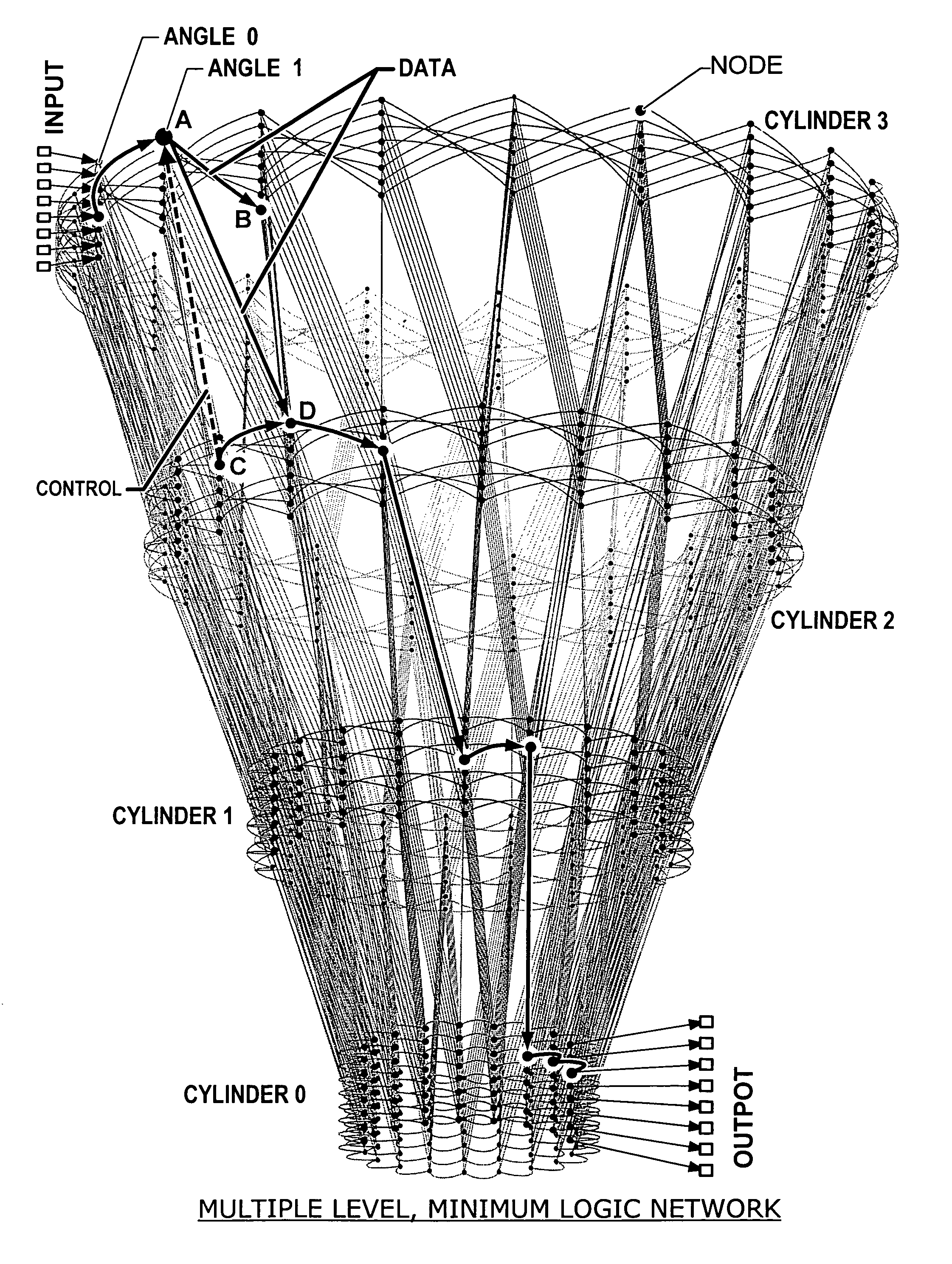
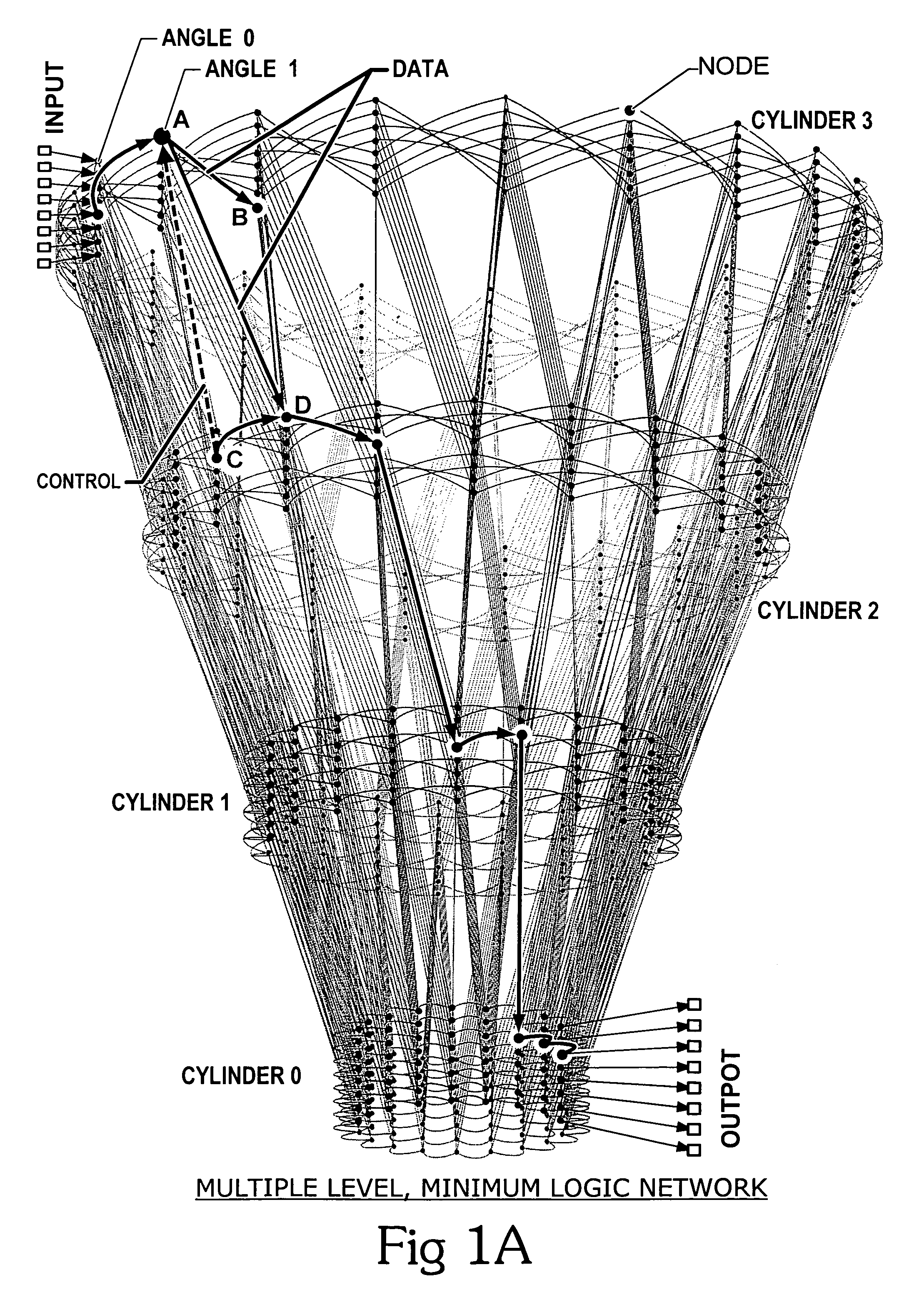
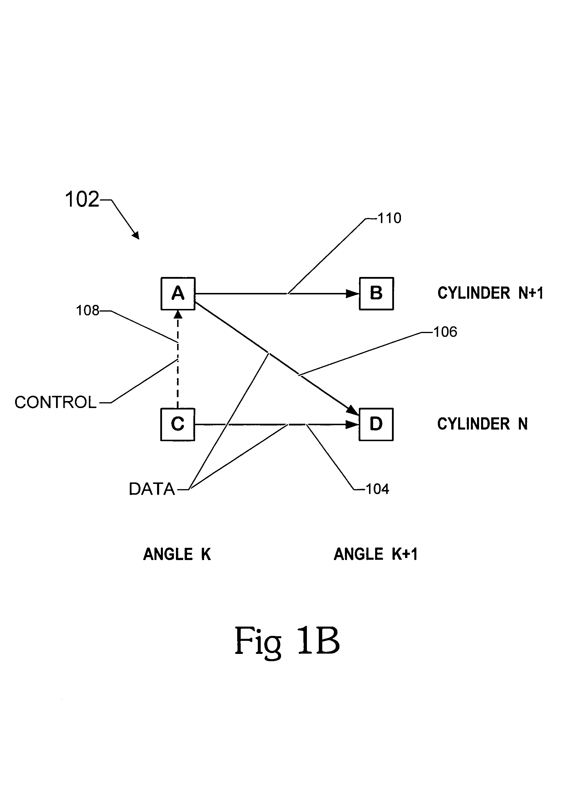
[0019]Referring to FIG. 1A, a schematic pictorial diagram illustrates a four-cylinder, eight-row network that exemplifies the multiple-level, minimum-logic (MLML) networks taught in U.S. Pat. No. 5,996,020. Data in the form of a serial packet enters the network at input terminals located at an outermost cylinder, shown as cylinder 3 at the top of FIG. 1A. Data packets move from node to node towards a target output port that is specified in the header of the packet. The description hereinafter refers to messages or data in terms of data units, typically in serial form, such as an interconnect protocol (IP) packets, Ethernet frames, ATM cells. Data may otherwise be termed switch-fabric segments, typically a portion of a larger frame or data packet, parallel computer inter-processor messages, or other data or messages that are limited in length. Data messages in the form of packets always move to a node at the next angle, and either stay at the same cylinder or move to a more inward cy...


PUM


Abstract

An interconnect structure and method of communicating messages on the interconnect structure assists high priority messages to travel through the interconnect structure at a faster rate than normal or low priority messages. An interconnect structure includes a plurality of nodes with a plurality of interconnect lines selectively coupling the nodes in a hierarchical multiple-level structure. Data moves from an uppermost source level to a lowermost destination level. Nodes in the structure are arranged in columns and levels. Data wormholes through the structure and, in a given time-step, data always moves from one column to an adjacent column and while remaining on the same level or moving down to a lower level. When data moves down a level, an additional bit of the target output is fixed so data exiting from the bottom of the structure arrives at the proper target output port.

Description

RELATED PATENTS AND APPLICATIONS[0001]This application is related to U.S. Pat. No. 6,289,021, which is incorporated herein by reference in its entirety. This application is also related to and incorporates U.S. Pat. No. 5,996,020 herein by reference in its entirety.[0002]The disclosed system and operating method are related to subject matter disclosed in the following co-pending patent applications that are incorporated by reference herein in their entirety:[0003]1. U.S. patent application Ser. No. 09 / 693,359 entitled, “Scaleable Multi-Path Wormhole Interconnect”, naming John Hesse as inventor and filed on even date herewith;[0004]2. U.S. patent application Ser. No. 09 / 693,603 entitled, “Scaleable Interconnect Structure for Parallel Computing and Parallel Memory Access”, naming John Hesse and Coke Reed as inventors and filed on even date herewith;[0005]3. U.S. Pat. No. 6,687,253 entitled, “Scaleable Wormhole Routing Concentrator”, naming Coke Reed and John Hesse as inventors and fil...

Claims


Application Information

Patent Timeline
IPC IPC(8): H04L12/28H04L12/56H04Q11/04
CPCH04L49/1553H04Q11/0478H04L2012/5651
Inventor REED, COKE S.HESSE, JOHN E.
Owner INTERACTIC HLDG LLC
Learn More