Heat actuated steering mount for maintaining frequency alignment in wavelength selective components for optical telecommunications

a technology of steering mount and frequency alignment, which is applied in the direction of mounting, optical light guide, instruments, etc., can solve the problems of changing the position of the optical channels on the mems element, the pointing of the beam impinging on the grating and the twisting of the grating itself, and the misalignment of the beam in the typical channel based telecommunications componen

Inactive Publication Date: 2006-03-21
NEOPHOTONICS CORP
View PDF2 Cites 12 Cited by
  • Summary
  • Abstract
  • Description
  • Claims
  • Application Information

AI Technical Summary

Problems solved by technology

However, thermal conditions in the operating environment can cause optical beams to become misaligned in typical channel based telecommunications components.
While the alignment of optical beams is usually stable at a fixed temperature, these devices will be exposed to wide temperature swings which can introduce a variety of types of errors in optical alignment, although the magnitude of error associated with each mechanism typically differs.
One mechanism which introduces error is thermo-elastic distortion of the optical housing that holds the optical components (lens, mirror, grating, waveplates, MEMS mirror arrays, etc.) in place, and can cause misalignment in the pointing of the beam impinging on the grating and the twisting of the grating itself.
This type of misalignment results in a change in the positions of the optical channels on the MEMS element.
Additional much smaller error mechanisms result from the change with temperature of the refractive index of the air and the glass making up the prisms used for the beam expander.
Moreover, a small error can result from variation in the grating pitch caused either by thermal expansion of the grating substrate or by thermo-elastic distortions of the metal grating mount applying a stress on the grating which distorts the grating.
Although the error mechanisms discussed above in the positioning

Method used


Image

  • Heat actuated steering mount for maintaining frequency alignment in wavelength selective components for optical telecommunications
  • Heat actuated steering mount for maintaining frequency alignment in wavelength selective components for optical telecommunications
  • Heat actuated steering mount for maintaining frequency alignment in wavelength selective components for optical telecommunications

Examples


Embodiment Construction

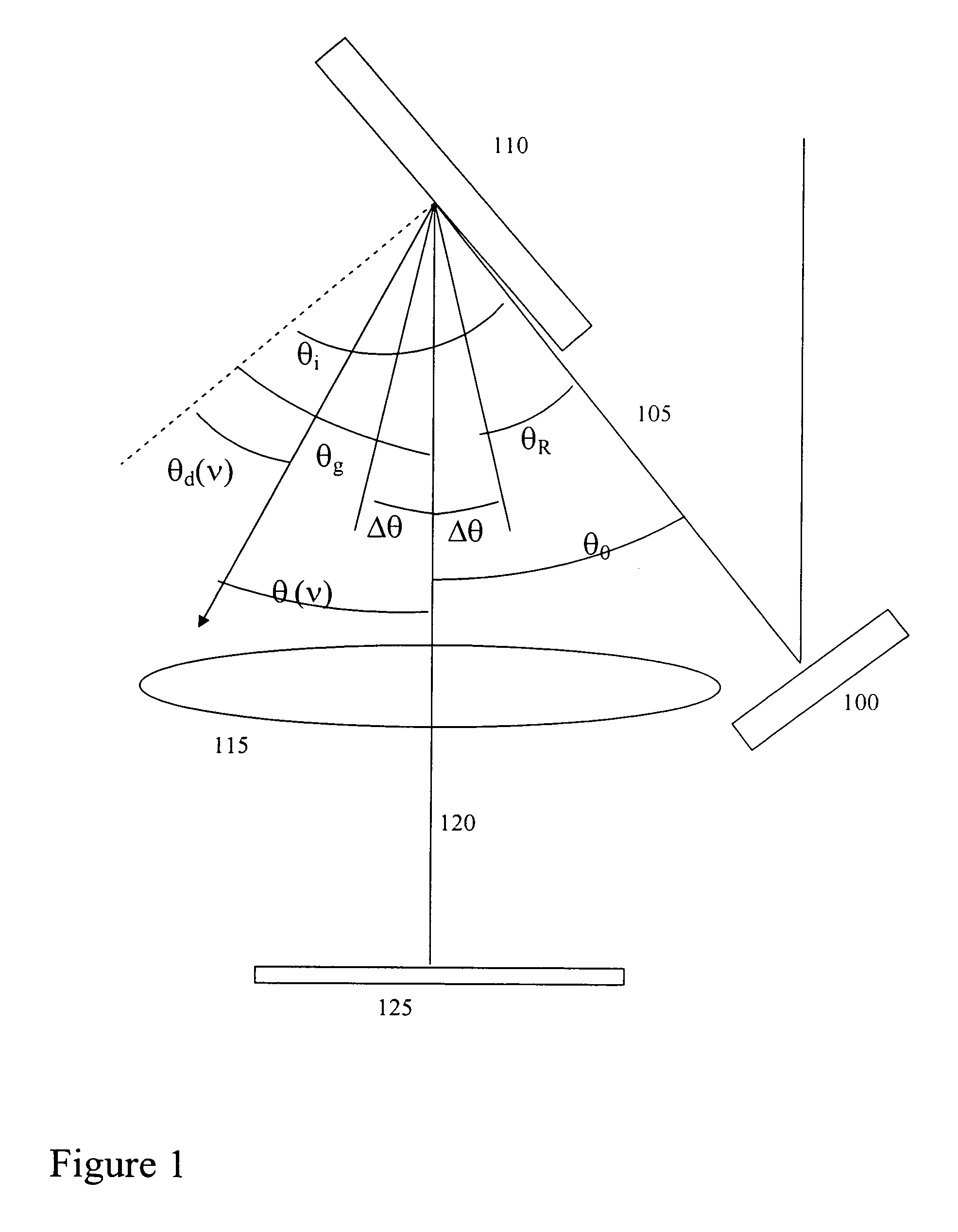
[0020]Referring first to FIG. 1, a greater understanding of the error mechanisms associated with the optical channel position on the MEMS array can be gained. As noted previously, multiple error mechanisms exist, all related to temperature variation, which can lead to misalignment of the optical beam including thermo-elastic distortion of the optical housing, changes in the refractive index of air within the optical channel, changes in the refractive index of the glass used for the prisms and grating pitch variation.

[0021]FIG. 1 shows a portion of an exemplary optical path including the position of the turning mirror 100, path between the mirror and the grating 105, grating 110, lens 115, central ray traveling from the grating through the center of the lens 120 and a MEMS actuator array 125. A complete depiction of an optical path is provided in U.S. patent application Ser. No. 10 / 371,907, entitled System and Method for Seamless Spectral Control and filed Feb. 20, 2003, and incorpor...


PUM


Abstract

A simple and robust heat actuated steering device for use with mirrors and other optical components of optical telecommunications equipment is described, together with systems which implement such devices. The device uses differential heating between two legs of a flexured mount to allow tilting that can be used to steer an optical beam. Disturbances in the optical alignment, caused by temperature changes, of an optical device containing this component can be compensated by measuring the device temperature and using this to determine a command signal, for example as provided through a lookup table, to correct for device misalignment. Techniques for calibrating the device and establishing the correction data are also disclosed.

Description

FIELD OF THE INVENTION[0001]This invention relates to methods and techniques for maintaining the frequency or wavelength alignment of optical components over a range of temperatures in optical telecommunications devices that control light at the optical channel level.BACKGROUND OF THE INVENTION[0002]Optical telecommunication components that work at the optical channel level such as Dynamic Channel Equalizers, Wavelength Blockers, Wavelength Selective Switches and similar devices often have alignment tolerances for optical beams of 50 μRad or less. Moreover, this alignment must be maintained over wide temperature swings, for example a temperature range of 75° C. In addition, this alignment must be maintained while sustaining large accelerations in any orientation. However, thermal conditions in the operating environment can cause optical beams to become misaligned in typical channel based telecommunications components. While the alignment of optical beams is usually stable at a fixed...

Claims


Application Information

Patent Timeline
IPC IPC(8): G02B6/00
CPCG02B6/4226G02B26/0866G02B7/1815G02B7/008
Inventor GODIL, ASIF A.GUSTAFSON, ERIC K.PATIL, RAJEEVSTOWE, TIMOTHY D.
Owner NEOPHOTONICS CORP
Why Eureka
Try Eureka